- 您現(xiàn)在的位置:買賣IC網(wǎng) > PDF目錄359790 > VS-500-LEF-HNN166.6286 (Vectron International, Inc.) Voltage Controlled SAW Oscillator PDF資料下載
參數(shù)資料
| 型號: | VS-500-LEF-HNN166.6286 |
| 廠商: | Vectron International, Inc. |
| 元件分類: | 振蕩器 |
| 英文描述: | Voltage Controlled SAW Oscillator |
| 中文描述: | 壓控SAW振蕩器 |
| 文件頁數(shù): | 2/8頁 |
| 文件大?。?/td> | 1297K |
| 代理商: | VS-500-LEF-HNN166.6286 |
VS-500 Voltage Controlled SAW Oscillator
Electrical Performance
Parameter
Frequency
Nominal Frequency
Absolute Pull Range
Linearity
Gain Transfer @ 155.52 MHz (See Pg 5/6)
Gain Transfer @ 622.08 MHz (See Pg 5/6)
Temperature Stability @ 155.52 MHz
Temperature Stability @ 622.08 MHz
Supply
Voltage
Current (No Load)
Outputs
Mid Level
Swing
Current
Rise & Fall Time
Symmetry
Spurious Suppression
Jitter @ 155.52 MHz (See Pg 5/6)
Jitter @ 622.08 MHz (See Pg 5/6)
Control Voltage
Input Impedance (LV-PECL or PECL)
Input Impedance (ECL)
Modulation Bandwidth
Operating Temperature
Package Size
Vectron International, 267 Lowell Rd, Hudson NH 03051-4916
Tel: 1-88-VECTRON-1 Website: www.vectron.com
Page 2 of 8
Rev: 14Nov03
Symbol Minimum
f
N
APR
Lin
K
V
K
V
f
STAB
f
STAB
V
CC
I
CC
I
OUT
t
R,
t
F
SYM
φ
J
φ
J
Z
c
Z
c
BW
T
OP
Typical
150 - 850
±
5
+691/+435
+434/+281
±
100
±
150
3.3/5.0
55
V
CC
-1.3
850
250
50
60
0.440
0.230
100
10
500
9.0 x 14.0 x 4.5
Maximum
3.63/5.5
80
V
CC
-1.1
20
400
55
85
Units
MHz
ppm
%
ppm/V
ppm/V
ppm
ppm
V
mA
V
mV-pp
mA
ps
%
dBc
ps-rms
ps-rms
k
k
kHz
°C
mm
Notes
1,2,3
1,2,3,9/10
2,4,9/10
2,9/10
2,9/10
1,6
1,6
2,3
3
2,3
2,3
6
5,6
2,3
6
6,7
6,8
6
6
6
1,3
±
50
2.97/4.5
V
CC
-1.5
45
50
-40
1. See Standard Frequencies and Ordering Information (Pg 8).
2. Parameters are tested with production test circuit below (Fig 2).
3. Parameters are tested at ambient temperature with test limits guardbanded for specified operating temperature.
4. Measured as the maximum deviation from the best straight-line fit, per MIL-0-55310.
5. Measured from 20% to 80% of a full output swing (Fig 1).
6. Not tested in production, guaranteed by design, verified at qualification.
7. Integrated across 12 kHz to 20 MHz, per GR-253-CORE Issue3.
8. Integrated across 50 kHz to 80 MHz, per GR-253-CORE Issue3.
9. Tested with Vc = 0.3V to 3.0V.
10. Tested with Vc = 0.5V to 4.5V.
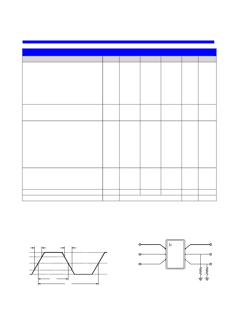
Figure 1. 10K LV-PECL Waveform
Figure 2. 3.3V Test Circuit
Vcc - 1.6V
Vcc - 1.3V
Vcc - 1.0V
80%
20%
t
R
t
F
t
A
t
B
SYM = 100 x t
A
/ t
B
2
5
50
50
Test Circuit Notes:
1) To Permit 50
Measurement of Outputs, all DC Inputs are Biased Down 1.3V.
2) All Voltage Sources Contain Bypass Capacitors to Minimize Supply Noise.
3) 50
Terminations are Within Test Equipment.
(-1.3V to +2V)
(-1.3V, Open)
(-1.3V)
(+2V)
COutput
Output
Disable, Enable
1
6
3
4
相關(guān)PDF資料 |
PDF描述 |
|---|---|
| VS-500-LEF-HNN167.3316 | Voltage Controlled SAW Oscillator |
| VS-500-LEF-HNN177.7371 | Voltage Controlled SAW Oscillator |
| VS-500-LEF-HNN311.0400 | Voltage Controlled SAW Oscillator |
| VS-500-LEF-HNN622.0800 | Voltage Controlled SAW Oscillator |
| VS-500-LEF-HNN624.7048 | Voltage Controlled SAW Oscillator |
相關(guān)代理商/技術(shù)參數(shù) |
參數(shù)描述 |
|---|---|
| VS-500-LEF-HNN167.3316 | 制造商:VECTRON 制造商全稱:Vectron International, Inc 功能描述:Voltage Controlled SAW Oscillator |
| VS-500-LEF-HNN177.7371 | 制造商:VECTRON 制造商全稱:Vectron International, Inc 功能描述:Voltage Controlled SAW Oscillator |
| VS-500-LEF-HNN311.0400 | 制造商:VECTRON 制造商全稱:Vectron International, Inc 功能描述:Voltage Controlled SAW Oscillator |
| VS-500-LEF-HNN622.0800 | 制造商:VECTRON 制造商全稱:Vectron International, Inc 功能描述:Voltage Controlled SAW Oscillator |
| VS-500-LEF-HNN624.7048 | 制造商:VECTRON 制造商全稱:Vectron International, Inc 功能描述:Voltage Controlled SAW Oscillator |
發(fā)布緊急采購,3分鐘左右您將得到回復(fù)。