- 您現(xiàn)在的位置:買賣IC網(wǎng) > PDF目錄359372 > VFC1506 (Vishay Intertechnology,Inc.) High Precision Flip Chip PDF資料下載
參數(shù)資料
| 型號: | VFC1506 |
| 廠商: | Vishay Intertechnology,Inc. |
| 英文描述: | High Precision Flip Chip |
| 中文描述: | 高精度倒裝芯片 |
| 文件頁數(shù): | 1/2頁 |
| 文件大?。?/td> | 115K |
| 代理商: | VFC1506 |
For technical questions in the Americas, contact foilsupport1@vishay.com
For technical questions in Asia/Japan/Europe/Africa/Israel, contact foilsupport2@vishay.com
www.vishay.com
N1
VFC1506
Vishay Foil Resistors
Document Number: 63083
Revision 13-Aug-04
ISRAEL: foilsales.israel@vishay.com FRANCE/SWITZERLAND/SOUTHERN EUROPE: foilsales.eusouth@vishay.com AMERICAS: foilsales.usa@vishay.com
ASIA/JAPAN: foilsales.asia@vishay.com UK/HOLLAND/SCANDANAVIA: foilsales.eunorth@vishay.com GERMANY/CZECH REPUBLIC/AUSTRIA: foilsales.eucentral@vishay.com
SALES
FEATURES
Nominal TCR: 0.5ppm/
°
C (- 55
°
C to + 125
°
C)
Resistance Range: 10
to 40k
Tolerance: to
±
0.01%
Load Life Stability:
±
0.01% maximum
R under full rated
power at + 70
°
C for 2000 hours
Shelf Life Stability: 50ppm (0.005%) over several years
Voltage Coefficient: < 0.00001%/volt (< 0.1ppm/V)
Current Noise: < 0.010
μ
V (rms)/volt of applied voltage
Non Inductive: < 0.08
Terminal Finishes Available:
Lead (Pb)-free (Sn 99.3% Cu 0.7%)
Tin/Lead Alloy (Sn 62% Pb 36% Ag 2%)
TABLE 1 - RESISTANCE VALUE VS
TOLERANCE AND TCR
VALUE
(
)
STANDARD
TOLERANCE (%)*
MAXIMUM
TCR**
100
to 40k
±
0.01
±
2.0ppm/
°
C
50
to < 100
±
0.05
±
3.0ppm/
°
C
25
to < 50
±
0.1
±
4.0ppm/
°
C
10
to < 25
*Tighter tolerances are available. Please contact Application
Engineering.
**Range; - 55
°
C to + 125
°
C, + 25
°
C reference.
±
0.25
±
5.0ppm/
°
C
TEST
MIL-PRF-55342
CHARACTERISTIC E MAXIMUM
R LIMITS*
VFC1506
R LIMITS**
Temperature Coefficient of
Resistance
Thermal Shock
Low Temperature Operation
Short Time Overload
High Temperature Exposure
Resistance to Bonding
Moisture Resistance
Life 2000hrs at + 70
°
C
±
25ppm/
°
C
See Table 1
±
0.10%
±
0.10%
±
0.10%
±
0.10%
±
0.20%
±
0.20%
±
0.50%
±
0.02%
±
0.02%
±
0.02%
±
0.03%
±
0.02%
±
0.03%
±
0.01%
TABLE 2 - TYPICAL PERFORMANCE SPECIFICATIONS
NOTES:
* As shown + 0.01
to allow for measurement error.
**As shown + 0.01
to allow for measurement error for values less
than 100
.
High Precision Flip Chip,
(Patents Pending in Industrialized Countries)
- 50
- 25
0
+ 25
+ 50
+ 75
+ 100
+ 125
+ 150
+ 100
+ 50
0
- 50
- 100
- 150
- 200
R
R
(PPM)
Ambient Temperature (
°
C)
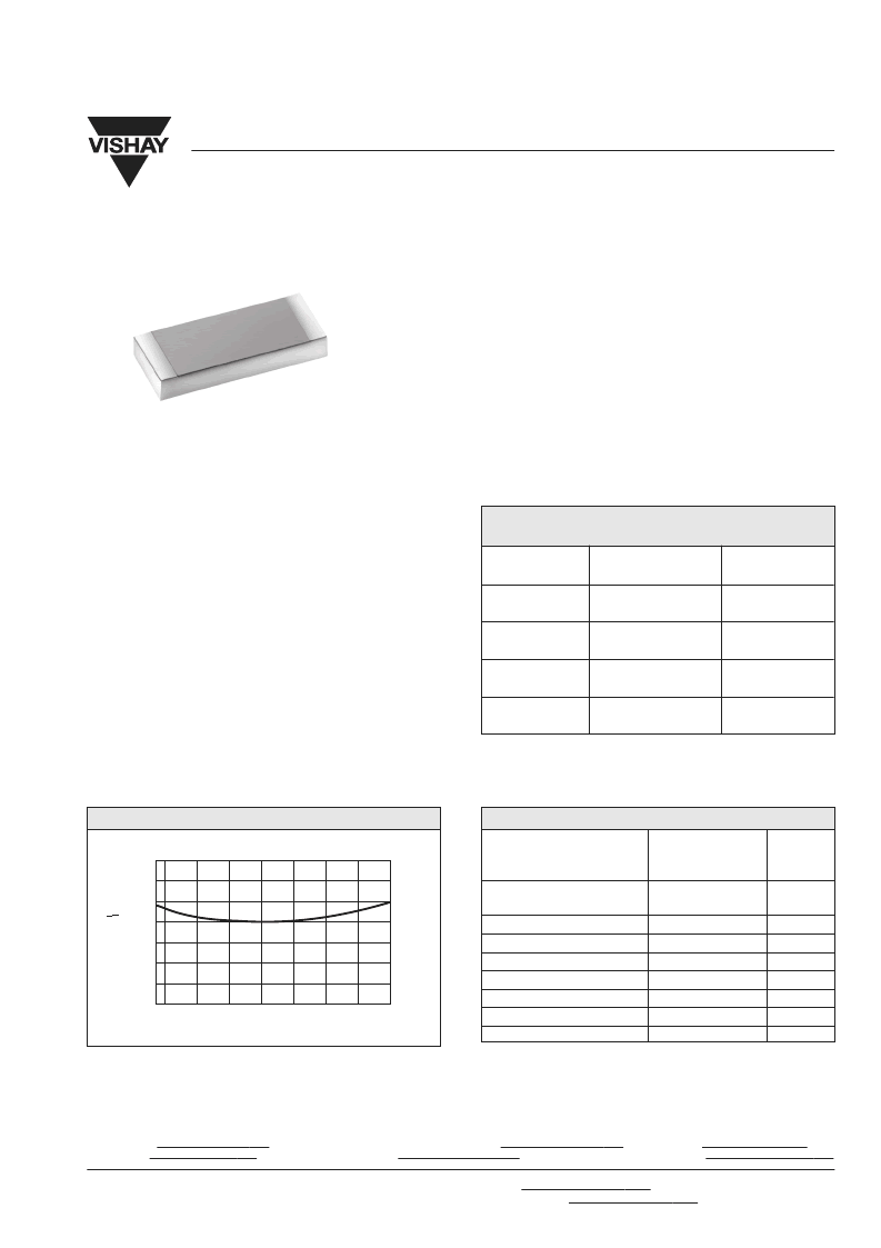
FIGURE 1 - NOMINAL TCR
Z FOIL
- 55
The TCR for values < 100
are influenced by the termination
composition and result in a deviation from this curve.
The VFC1506 is a surface mountable flip chip resistor that
utilizes Ultra Precision Bulk Metal
“Z” Foil. This product
differs from other Vishay Bulk Metal
Foil surface mount
devices in as much as it is installed with the foil side facing
the PCB providing better power handling capabilities. The
Foil element is isolated from the PCB by a protective
overcoating. This overcoating plus the overall product design
isolates the resistor from handling and installation stresses.
The temperature coefficient of resistance (TCR) curve below
shows the new revolutionary “Z” Foil with its nominal TCR
of 0.5ppm/
°
C. The Bulk Metal
Foil characteristics of
excellent long term stability, low noise and availability of tight
tolerance are maintained in this Flip Chip configuration. The
VFC1506 is available in any value within the specified
resistance range. The flip chip configuration is more
economical for high volume, analog applications where high
precision is required.
Z Foil 0.5PPM/
°
C
Product may not
be to scale
相關(guān)PDF資料 |
PDF描述 |
|---|---|
| VFC3802H | Voltage-to-Frequency Converter |
| VFC3805H | Voltage-to-Frequency Converter |
| VFC3810H | Voltage-to-Frequency Converter |
| VFD-L | User Manual |
| VFFC-1-0 | HEAT SHRINK BLK 5M |
相關(guān)代理商/技術(shù)參數(shù) |
參數(shù)描述 |
|---|---|
| VFC180SA | 制造商:SYNERGY 制造商全稱:SYNERGY MICROWAVE CORPORATION 功能描述:VOLTAGE CONTROLLED OSCILLATORS |
| VFC1850SA | 制造商:SYNERGY 制造商全稱:SYNERGY MICROWAVE CORPORATION 功能描述:VOLTAGE CONTROLLED OSCILLATORS |
| VFC210SA | 制造商:SYNERGY 制造商全稱:SYNERGY MICROWAVE CORPORATION 功能描述:VOLTAGE CONTROLLED OSCILLATORS |
| VFC-2125 | 制造商:Quest Technology International Inc 功能描述: |
| VFC219SA | 制造商:SYNERGY 制造商全稱:SYNERGY MICROWAVE CORPORATION 功能描述:VOLTAGE CONTROLLED OSCILLATORS |
發(fā)布緊急采購,3分鐘左右您將得到回復。