- 您現(xiàn)在的位置:買賣IC網(wǎng) > PDF目錄200646 > UQQ-24/4-Q12P9L1-C (CD TECHNOLOGIES INC) 1-OUTPUT 96 W DC-DC REG PWR SUPPLY MODULE PDF資料下載
參數(shù)資料
| 型號(hào): | UQQ-24/4-Q12P9L1-C |
| 廠商: | CD TECHNOLOGIES INC |
| 元件分類: | 電源模塊 |
| 英文描述: | 1-OUTPUT 96 W DC-DC REG PWR SUPPLY MODULE |
| 封裝: | ROHS COMPLIANT PACKAGE-9 |
| 文件頁數(shù): | 2/17頁 |
| 文件大小: | 1988K |
| 代理商: | UQQ-24/4-Q12P9L1-C |
MDC_UQQ_A03 Page 0 of 7
UQQ Series
Wide Input Range Single Output DC/DC Converters
D C / D C C O N V E R T E R S
Technical enquiries email: sales@murata-ps.com, tel: + 508 339 3000
www.murata-ps.com
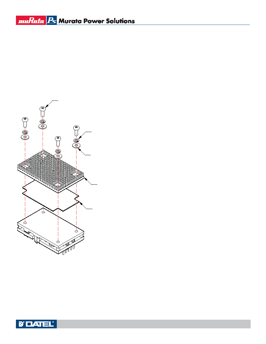
Figure 7. Model UQQ Heatsink Assembly Diagram
alternative. The UQQ’s are available with a low-profile extruded aluminum
heatsink kit, models HS-QB25-UVQ, HS-QB50-UVQ, and HS-QB00-UVQ.
This kit includes the heatsink, thermal mounting pad, screws and mounting
hardware. See the assembly diagram below. Do not overtighten the screws in
the tapped holes in the converter. This kit adds excellent thermal performance
without sacrificing too much component height. See the Mechanical Outline
Drawings for assembled dimensions. If the thermal pad is firmly attached, no
thermal compound (“thermal grease”) is required.
When assembling these kits onto the converter, include ALL kit hardware to
assure adequate mechanical capture and proper clearances. Thread relief is
0.090" (2.3mm).
Be aware that we need to handle only the internal heat dissipation, not the full
power output of the converter. This internal heat dissipation is related to the
efficiency as follows:
Power Dissipation [Pd] = Power In – Power Out [1]
Power Out / Power In = Efficiency [in %] / 100 [2]
Power Dissipation [Pd] = Power In x (1 –Efficiency%/100) [3]
Power Dissipation [Pd] = Power Out x (1 / (Efficiency%/100) - 1) [4]
Efficiency of course varies with input voltage and the total output power. Please
refer to the Performance Curves.
Since many applications do include fans, here is an approximate equation to
calculate the net thermal resistance:
RQ [at airflow] = RQ [natural convection] / (1 + (Airflow in LFM) x
[Airflow Constant]) [5]
Where,
R
Q [at airflow] is the net thermal resistance (in °C/W) with the amount of
airflow available and,
R
Q [natural convection] is the still air total path thermal resistance or in this
case 2.5°C/Watt and,
“Airflow in LFM” is the net air movement flow rate immediately at the converter.
This equation simplifies an otherwise complex aerodynamic model but is a
useful starting point. The “Airflow Constant” is dependent on the fan and enclo-
sure geometry. For example, if 200 LFM of airflow reduces the effective natural
convection thermal resistance by one half, the airflow constant would be
0.005. There is no practical way to publish a “one size fits all” airflow constant
because of variations in airflow direction, heatsink orientation, adjacent walls,
enclosure geometry, etc. Each application must be determined empirically and
the equation is primarily a way to help understand the cooling arithmetic.
This equation basically says that small amounts of forced airflow are quite
effective removing the heat. But very high airflows give diminishing returns.
Conversely, no forced airflow causes considerable heat buildup. At zero airflow,
cooling occurs only because of natural convection over the heatsink. Natural
convection is often well below 50 LFM, not much of a breeze.
While these equations are useful as a conceptual aid, most users find it very
difficult to measure actual airflow rates at the converter. Even if you know
the velocity specifications of the fan, this does not usually relate directly to
the enclosure geometry. Be sure to use a considerable safety margin doing
thermal analysis. If in doubt, measure the actual heat sink temperature with
a calibrated thermocouple, RTD or thermistor. Safe operation should keep the
heat sink below 00°C.
Calculating Maximum Power Dissipation
To determine the maximum amount of internal power dissipation, find the
ambient temperature inside the enclosure and the airflow (in Linear Feet per
Minute – LFM) at the converter. Determine the expected heat dissipation using
the Efficiency curves and the converter Input Voltage. You should also compen-
sate for lower atmospheric pressure if your application altitude is considerably
above sea level.
Thermal Performance
The HS-QB25-UVQ heatsink has a thermal resistance of 2 degrees Celsius
per Watt of internal heat dissipation with “natural convection” airflow (no
fans or other mechanical airflow) at sea level altitude. This thermal resistance
assumes that the heatsink is firmly attached using the supplied thermal pad
and that there is no nearby wall or enclosure surface to inhibit the airflow. The
thermal pad adds a negligible series resistance of approximately 0.5°C/Watt so
that the total assembled resistance is 2.5°C/Watt.
相關(guān)PDF資料 |
PDF描述 |
|---|---|
| UQQ-3.3/25-Q12P9-C | 1-OUTPUT 82.5 W DC-DC REG PWR SUPPLY MODULE |
| UQQ-3.3/25-Q48NB9-C | 1-OUTPUT 82.5 W DC-DC REG PWR SUPPLY MODULE |
| UR1111C | SINGLE COLOR LED, RED, 1.2 mm |
| UB1111C | SINGLE COLOR LED, BLUE, 1.2 mm |
| UR3864X | T-1 SINGLE COLOR LED, RED, 3 mm |
相關(guān)代理商/技術(shù)參數(shù) |
參數(shù)描述 |
|---|---|
| UQQ-3.3/25-Q12NB-C | 功能描述:DC/DC轉(zhuǎn)換器 12Vin 3.3Vout 25A neg TH baseplate RoHS:否 制造商:Murata 產(chǎn)品: 輸出功率: 輸入電壓范圍:3.6 V to 5.5 V 輸入電壓(標(biāo)稱): 輸出端數(shù)量:1 輸出電壓(通道 1):3.3 V 輸出電流(通道 1):600 mA 輸出電壓(通道 2): 輸出電流(通道 2): 安裝風(fēng)格:SMD/SMT 封裝 / 箱體尺寸: |
| UQQ-3.3/25-Q12N-C | 功能描述:DC/DC轉(zhuǎn)換器 12Vin 3.3Vout 25A neg polarity TH RoHS:否 制造商:Murata 產(chǎn)品: 輸出功率: 輸入電壓范圍:3.6 V to 5.5 V 輸入電壓(標(biāo)稱): 輸出端數(shù)量:1 輸出電壓(通道 1):3.3 V 輸出電流(通道 1):600 mA 輸出電壓(通道 2): 輸出電流(通道 2): 安裝風(fēng)格:SMD/SMT 封裝 / 箱體尺寸: |
| UQQ-3.3/25-Q12PB-C | 功能描述:DC/DC轉(zhuǎn)換器 12Vin 3.3Vout 25A pos TH baseplate RoHS:否 制造商:Murata 產(chǎn)品: 輸出功率: 輸入電壓范圍:3.6 V to 5.5 V 輸入電壓(標(biāo)稱): 輸出端數(shù)量:1 輸出電壓(通道 1):3.3 V 輸出電流(通道 1):600 mA 輸出電壓(通道 2): 輸出電流(通道 2): 安裝風(fēng)格:SMD/SMT 封裝 / 箱體尺寸: |
| UQQ-3.3/25-Q12PB-C | 制造商:Murata Power Solutions 功能描述:DC/DC Converter |
| UQQ-3.3/25-Q12P-C | 功能描述:DC/DC轉(zhuǎn)換器 12Vin 3.3Vout 25A pos polarity TH RoHS:否 制造商:Murata 產(chǎn)品: 輸出功率: 輸入電壓范圍:3.6 V to 5.5 V 輸入電壓(標(biāo)稱): 輸出端數(shù)量:1 輸出電壓(通道 1):3.3 V 輸出電流(通道 1):600 mA 輸出電壓(通道 2): 輸出電流(通道 2): 安裝風(fēng)格:SMD/SMT 封裝 / 箱體尺寸: |
發(fā)布緊急采購,3分鐘左右您將得到回復(fù)。