- 您現(xiàn)在的位置:買賣IC網(wǎng) > PDF目錄384046 > UPD784907GF (NEC Corp.) 16-BIT SINGLE-CHIP MICROCONTROLLER PDF資料下載
參數(shù)資料
| 型號: | UPD784907GF |
| 廠商: | NEC Corp. |
| 英文描述: | 16-BIT SINGLE-CHIP MICROCONTROLLER |
| 中文描述: | 16位單片機 |
| 文件頁數(shù): | 54/98頁 |
| 文件大?。?/td> | 657K |
| 代理商: | UPD784907GF |
第1頁第2頁第3頁第4頁第5頁第6頁第7頁第8頁第9頁第10頁第11頁第12頁第13頁第14頁第15頁第16頁第17頁第18頁第19頁第20頁第21頁第22頁第23頁第24頁第25頁第26頁第27頁第28頁第29頁第30頁第31頁第32頁第33頁第34頁第35頁第36頁第37頁第38頁第39頁第40頁第41頁第42頁第43頁第44頁第45頁第46頁第47頁第48頁第49頁第50頁第51頁第52頁第53頁當(dāng)前第54頁第55頁第56頁第57頁第58頁第59頁第60頁第61頁第62頁第63頁第64頁第65頁第66頁第67頁第68頁第69頁第70頁第71頁第72頁第73頁第74頁第75頁第76頁第77頁第78頁第79頁第80頁第81頁第82頁第83頁第84頁第85頁第86頁第87頁第88頁第89頁第90頁第91頁第92頁第93頁第94頁第95頁第96頁第97頁第98頁
μ
PD784907, 784908
54
Data Sheet U11680EJ2V0DS00
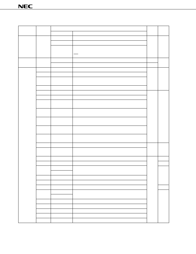
Table 9-2. Interrupt Source
Type
Default
Priority
Source
Internal/
External Service
Macro
Name
Trigger
Software
—
BRK instruction
Instruction execution
—
—
BRKCS instruction Instruction execution
Operand error
When the MOV STBC,#byte, MOV WDM,#byte, or LOCATION
instruction is executed, exclusive OR of the byte operand and
byte does not produce FFH.
Non-maskable
—
NMI
Detection of edge input on the pin
External
—
WDT
Watchdog timer overflow
Internal
Maskable
0 (highest) INTP0
Detection of edge input on the pin (TM1/TM1W capture trigger) External
√
1
INTP1
Detection of edge input on the pin (TM2/TM2W capture trigger)
2
INTP2
Detection of edge input on the pin (TM2/TM2W event counter
input)
3
INTP3
Detection of edge input on the pin (TM0 capture trigger)
4
INTC00
TM0-CR00 match signal issued
Internal
√
5
INTC01
TM0-CR01 match signal issued
6
INTC10
TM1-CR10 match signal issued (in 8-bit operation mode)
TM1W-CR10W match signal issued (in 16-bit operation mode)
7
INTC11
TM1-CR11 match signal issued (in 8-bit operation mode)
TM1W-CR11W match signal issued (in 16-bit operation mode)
8
INTC20
TM2-CR20 match signal issued (in 8-bit operation mode)
TM2W-CR20W match signal issued (in 16-bit operation mode)
9
INTC21
TM2-CR21 match signal issued (in 8-bit operation mode)
TM2W-CR21W match signal issued (in 16-bit operation mode)
10
INTC30
TM3-CR30 match signal issued (in 8-bit operation mode)
TM3W-CR30W match signal issued (in 16-bit operation mode)
11
INTP4
Detection of edge input on the pin
External
√
12
INTP5
Detection of edge input on the pin
(A/D converter start conversion trigger)
13
INTAD
A/D converter processing completed (ADCR transfer)
Internal
√
14
INTSER
ASI0 reception error
—
15
INTSR
ASI0 reception completed or CSI1 transfer completed
√
INTCSI1
16
INTST
ASI0 transmission completed
17
INTCSI
CSI0 transfer completed
18
INTSER2
ASI2 reception error
—
19
INTSR2
ASI2 reception completed or CSI2 transfer completed
√
INTCSI2
20
INTST2
ASI2 transmission completed
21
INTIE1
IEBus data access request
22
INTIE2
IEBus communication error and communication start/end
23
INTW
Clock timer output
24 (lowest) INTCSI3
CSI3 transfer completed
Remark
ASI: Asynchronous serial interface
CSI: Clocked serial interface
相關(guān)PDF資料 |
PDF描述 |
|---|---|
| UPD784908 | 16-BIT SINGLE-CHIP MICROCONTROLLER |
| UPD784908GF | 16-BIT SINGLE-CHIP MICROCONTROLLER |
| UPD784908GF-XXX-3BA | 16-Bit Microcontroller |
| UPD784907GF-XXX-3BA | 16-Bit Microcontroller |
| UPD784915A | 16-BIT SINGLE-CHIP MICROCONTROLLERS |
相關(guān)代理商/技術(shù)參數(shù) |
參數(shù)描述 |
|---|---|
| UPD784935AGF-113-3BA | 制造商:NEC Electronics Corporation 功能描述: |
| UPD784938AGF-188-3BA | 制造商:NEC Electronics Corporation 功能描述: |
| UPD789104AMC(A)-968-5A4-E2 | 制造商:Renesas Electronics Corporation 功能描述: |
| UPD789104AMC-671-5A4-E1 | 制造商:Renesas Electronics Corporation 功能描述: |
| UPD789104AMC-672-5A4-E1 | 制造商:Renesas Electronics Corporation 功能描述: |
發(fā)布緊急采購,3分鐘左右您將得到回復(fù)。