- 您現(xiàn)在的位置:買賣IC網(wǎng) > PDF目錄383979 > UPD16682P (NEC Corp.) 1/65 DUTY LCD CONTROLLER/DRIVER WITH ON-CHIP RAM PDF資料下載
參數(shù)資料
| 型號(hào): | UPD16682P |
| 廠商: | NEC Corp. |
| 英文描述: | 1/65 DUTY LCD CONTROLLER/DRIVER WITH ON-CHIP RAM |
| 中文描述: | 1 / 65稅LCD控制器/驅(qū)動(dòng)器,片內(nèi)RAM |
| 文件頁數(shù): | 20/56頁 |
| 文件大?。?/td> | 435K |
| 代理商: | UPD16682P |
第1頁第2頁第3頁第4頁第5頁第6頁第7頁第8頁第9頁第10頁第11頁第12頁第13頁第14頁第15頁第16頁第17頁第18頁第19頁當(dāng)前第20頁第21頁第22頁第23頁第24頁第25頁第26頁第27頁第28頁第29頁第30頁第31頁第32頁第33頁第34頁第35頁第36頁第37頁第38頁第39頁第40頁第41頁第42頁第43頁第44頁第45頁第46頁第47頁第48頁第49頁第50頁第51頁第52頁第53頁第54頁第55頁第56頁
Data Sheet S13368EJ3V0DS00
20
μ
PD16682
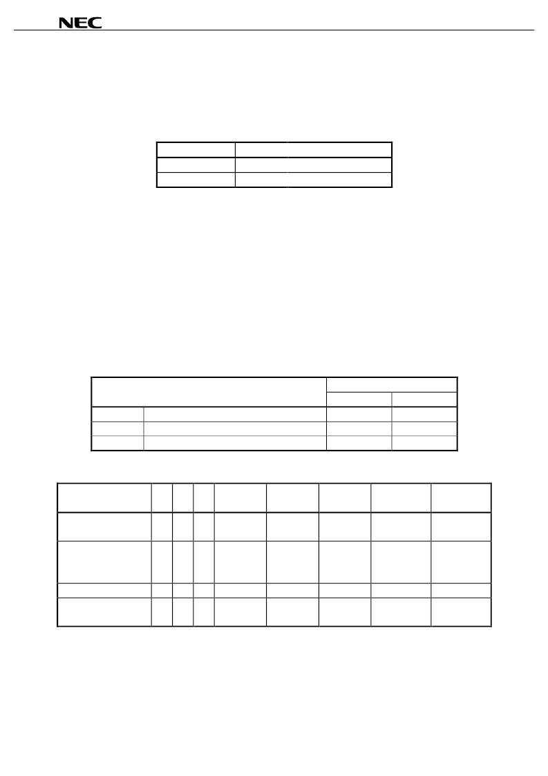
9. COMMON OUTPUT STATUS SELECT CIRCUIT
With the
μ
PD16682, the common output status select command can be used to set the scan direction for COM
outputs (see Table 9
1). As a result, there are fewer IC layout constraints when setting up the LCD module.
Table 9
1. Setting of Scan Direction for COM Outputs
Status
COM Scan Direction
Normal (forward)
COM
0
→
COM
63
Inverted (reverse)
COM
63
→
COM
0
10. POWER SUPPLY CIRCUIT
10.1 Power Supply Circuit
The power supply circuit, which supplies the voltage needed to drive the LCD, includes a booster circuit, voltage
regulator circuit, and voltage follower circuit.
The power control set command is used to control the ON/OFF status of the power supply circuit’s booster circuit,
voltage regulator circuit (V regulator circuit), and voltage follower circuit (V/F circuit). This makes it possible to jointly
use an external power supply along with certain functions of the on-chip power supply. Table 10
1 shows the
function that controls the 3-bit data in the power control set command and Table 10
2 shows a reference chart of
combinations.
Table 10
1. Control Values Set to Bits in Power Control Set Command
Item
Status
H
L
D
2
Booster circuit control bit
ON
OFF
D
1
Voltage regulator circuit control bit
ON
OFF
D
0
Voltage follower circuit control bit
ON
OFF
Table 10
2. Reference Chart of Combinations
Use Status
D
2
D
1
D
0
Booster
Circuit
V Regulator
Circuit
V/F Circuit
External Power
Supply Input
Booster-
related Pin
<1> Use on-chip power
supply
H
H
H
{
{
{
V
DD2
Used
<2> Use V regulator
circuit and V/F circuit
only
L
H
H
×
{
{
V
LCD
Open
<3> Use V/F circuit only
L
L
H
×
×
{
V
LC1
Open
<4> Use External power
supply only
Remarks 1.
The booster-related pins are indicated as pins C
1+
, C
1–
, C
2+
, C
2–
, C
3+
, and C
3–
.
2.
Although combinations other than those shown above are possible, they have no practical uses and
L
L
L
×
×
×
V
LC1
to V
LC5
Open
therefore cannot be recommended.
相關(guān)PDF資料 |
PDF描述 |
|---|---|
| UPD16682W | 1/65 DUTY LCD CONTROLLER/DRIVER WITH ON-CHIP RAM |
| UPD16700 | 256-OUTPUT TFT-LCD GATE DRIVER |
| UPD16700N | DUSTCAP, METAL SZ22; Material:Zinc Alloy; Colour:Nickel Plated; Connector shell size:22; Voltage rating, AC:750V; Series:TRIM TRIO |
| UPD16803 | MONOLITHIC DUAL H BRIDGE DRIVER CIRCUIT |
| UPD16803GS | MONOLITHIC DUAL H BRIDGE DRIVER CIRCUIT |
相關(guān)代理商/技術(shù)參數(shù) |
參數(shù)描述 |
|---|---|
| UPD16682P-001 | 制造商:未知廠家 制造商全稱:未知廠家 功能描述:LCD Display Driver |
| UPD16682P-002 | 制造商:未知廠家 制造商全稱:未知廠家 功能描述:LCD Display Driver |
| UPD16682P-003 | 制造商:未知廠家 制造商全稱:未知廠家 功能描述:LCD Display Driver |
| UPD16682P-004 | 制造商:未知廠家 制造商全稱:未知廠家 功能描述:LCD Display Driver |
| UPD16682W | 制造商:NEC 制造商全稱:NEC 功能描述:1/65 DUTY LCD CONTROLLER/DRIVER WITH ON-CHIP RAM |
發(fā)布緊急采購,3分鐘左右您將得到回復(fù)。