- 您現(xiàn)在的位置:買賣IC網(wǎng) > PDF目錄383976 > UPC1853 (NEC Corp.) CONN SEALING FOR WALL RCPT #14 PDF資料下載
參數(shù)資料
| 型號: | UPC1853 |
| 廠商: | NEC Corp. |
| 英文描述: | CONN SEALING FOR WALL RCPT #14 |
| 中文描述: | 矩陣環(huán)繞集成電路I2C總線 |
| 文件頁數(shù): | 60/76頁 |
| 文件大小: | 544K |
| 代理商: | UPC1853 |
第1頁第2頁第3頁第4頁第5頁第6頁第7頁第8頁第9頁第10頁第11頁第12頁第13頁第14頁第15頁第16頁第17頁第18頁第19頁第20頁第21頁第22頁第23頁第24頁第25頁第26頁第27頁第28頁第29頁第30頁第31頁第32頁第33頁第34頁第35頁第36頁第37頁第38頁第39頁第40頁第41頁第42頁第43頁第44頁第45頁第46頁第47頁第48頁第49頁第50頁第51頁第52頁第53頁第54頁第55頁第56頁第57頁第58頁第59頁當前第60頁第61頁第62頁第63頁第64頁第65頁第66頁第67頁第68頁第69頁第70頁第71頁第72頁第73頁第74頁第75頁第76頁
6
μ
P
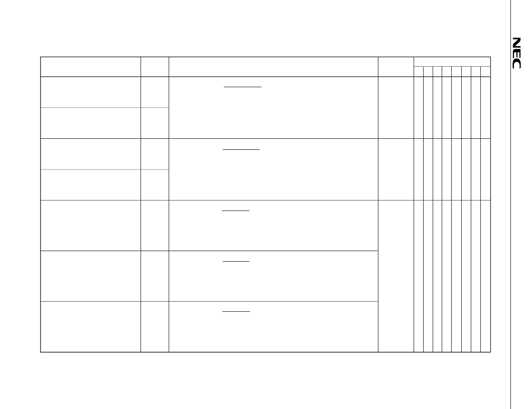
Matrix surround block
(1/3)
Parameter
Symbol
Test conditions
Subaddress
Data
D7 D6 D5 D4 D3 D2 D1 D0
In-phase gain
G
MOV1
Response = 20 log
L input
L1, R1 output
08
1
1
0
0
1
0
0
0
Movie mode 1
L1, R1 output: Output signal level of pin 14 or 13.
In-phase gain
G
MOV2
L input: Input signal level of pin 26.
Movie mode 2
Pin 26: Input SIN wave (1 kHz, 0.5 V
rms
).
Pin 27: No signal (Connect to GND with an input coupling capacitor).
In-phase gain
G
MUS1
Response = 20 log
L input
L1, R1 output
08
1
1
1
0
1
0
0
0
Music mode 1
L1, R1 output: Output signal level of pin 14 or 13.
In-phase gain
G
MUS2
L input: Input signal level of pin 26.
Music mode 2
Pin 26: Input SIN wave (1 kHz, 0.5 V
rms
).
Pin 27: No signal (Connect to GND with an input coupling capacitor).
In-phase gain
G
SIML1
Response = 20 log
L, R input
L1 output
08
1
1
0
1
1
0
0
0
Simulated mode
(L-ch) 1
L1 output
: Output signal level of pin 14.
L, R input: Input signal level of pin 26 or 27.
Pins 26 and 27: Input SIN wave (250 Hz, 0.5 V
rms
).
In-phase gain
G
SIML2
Response = 20 log
L, R input
L1 output
Simulated mode
(L-ch) 2
L1 output
: Output signal level of pin 14.
L, R input: Input signal level of pin 26 or 27.
Pins 26 and 27: Input SIN wave (1 kHz, 0.5 V
rms
).
In-phase gain
G
SIML3
Response = 20 log
L, R input
L1 output
Simulated mode
(L-ch) 3
L1 output
: Output signal level of pin 14.
L, R input: Input signal level of pin 26 or 27.
Pins 26 and 27: Input SIN wave (4 kHz, 0.5 V
rms
).
Remark
The methods are common to both the
μ
PC1853CT-01 and
μ
PC1853CT-02.
相關PDF資料 |
PDF描述 |
|---|---|
| UPC1857 | SOUND CONTROL IC WITH SURROUND AND I2C BUS |
| UPC1857ACT | SOUND CONTROL IC WITH SURROUND AND I2C BUS |
| UPC1857A | CONN SEALING FOR WALL RCPT #24 |
| UPC1876GT | US MTS DECODER |
| UPC1876 | US MTS DECODER |
相關代理商/技術參數(shù) |
參數(shù)描述 |
|---|---|
| UPC1853CT | 制造商:未知廠家 制造商全稱:未知廠家 功能描述:Surround-Sound Processor |
| UPC1853CT-01 | 制造商:NEC Electronics Corporation 功能描述: |
| UPC1853CT-02 | 制造商:NEC 制造商全稱:NEC 功能描述:MATRIX SURROUND IC WITH I2C BUS |
| UPC1854A | 制造商:NEC 制造商全稱:NEC 功能描述:I2C BUS-COMPATIBLE US MTS PROCESSING LSI |
| UPC1854ACT | 制造商:NEC 制造商全稱:NEC 功能描述:I2C BUS-COMPATIBLE US MTS PROCESSING LSI |
發(fā)布緊急采購,3分鐘左右您將得到回復。