- 您現(xiàn)在的位置:買賣IC網(wǎng) > PDF目錄199476 > TS87C51RD2-VCLD 8-BIT MICROCONTROLLER PDF資料下載
參數(shù)資料
| 型號: | TS87C51RD2-VCLD |
| 元件分類: | 8位微控制器 |
| 英文描述: | 8-BIT MICROCONTROLLER |
| 中文描述: | 8位微控制器 |
| 文件頁數(shù): | 32/74頁 |
| 文件大?。?/td> | 689K |
| 代理商: | TS87C51RD2-VCLD |
第1頁第2頁第3頁第4頁第5頁第6頁第7頁第8頁第9頁第10頁第11頁第12頁第13頁第14頁第15頁第16頁第17頁第18頁第19頁第20頁第21頁第22頁第23頁第24頁第25頁第26頁第27頁第28頁第29頁第30頁第31頁當(dāng)前第32頁第33頁第34頁第35頁第36頁第37頁第38頁第39頁第40頁第41頁第42頁第43頁第44頁第45頁第46頁第47頁第48頁第49頁第50頁第51頁第52頁第53頁第54頁第55頁第56頁第57頁第58頁第59頁第60頁第61頁第62頁第63頁第64頁第65頁第66頁第67頁第68頁第69頁第70頁第71頁第72頁第73頁第74頁
38
Rev. C - 06 March, 2001
TS80C51RA2/RD2
TS83C51RB2/RC2/RD2
TS87C51RB2/RC2/RD2
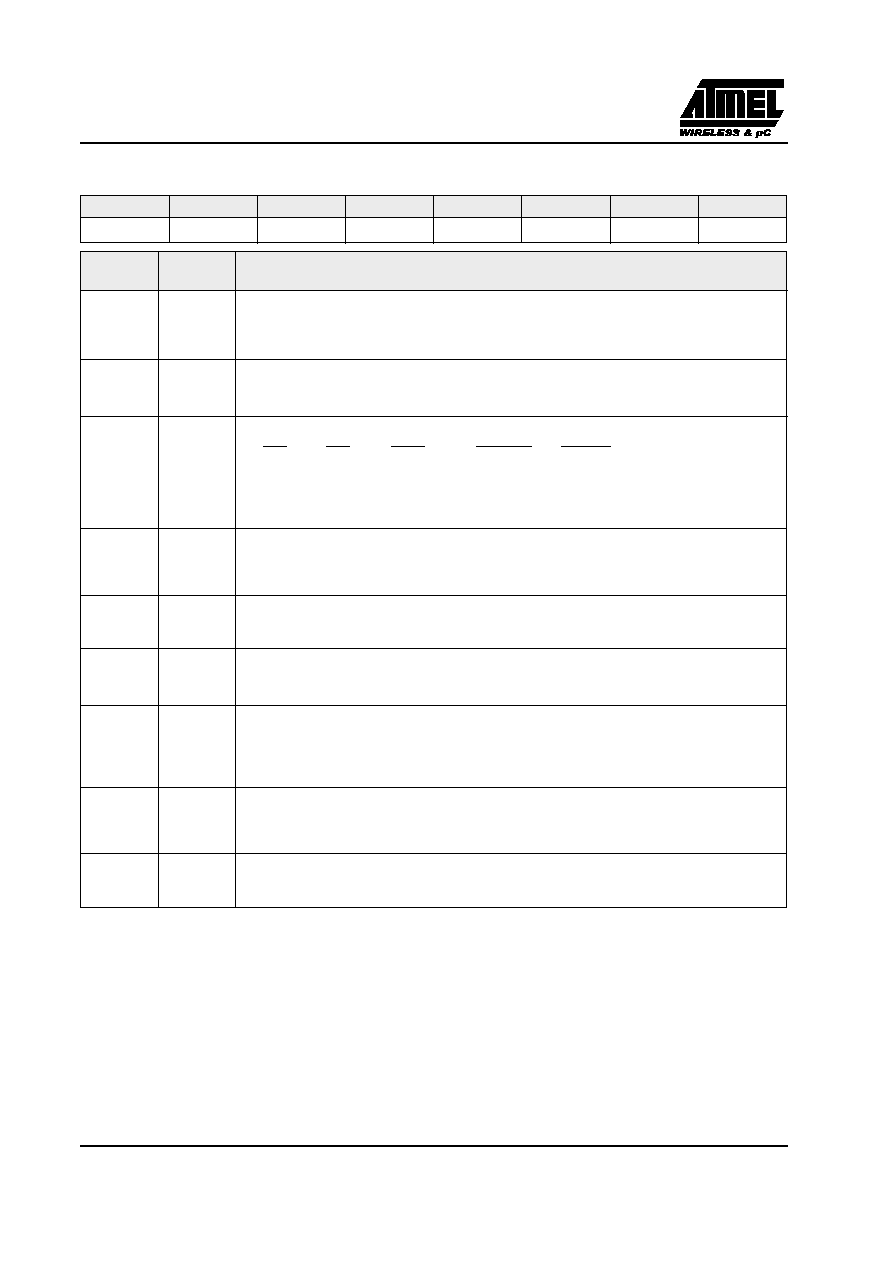
Table 16. SCON Register
SCON - Serial Control Register (98h)
Reset Value = 0000 0000b
Bit addressable
7
6
5
4
3
2
1
0
FE/SM0
SM1
SM2
REN
TB8
RB8
TI
RI
Bit Number
Bit
Mnemonic
Description
7
FE
Framing Error bit (SMOD0=1)
Clear to reset the error state, not cleared by a valid stop bit.
Set by hardware when an invalid stop bit is detected.
SMOD0 must be set to enable access to the FE bit
SM0
Serial port Mode bit 0
Refer to SM1 for serial port mode selection.
SMOD0 must be cleared to enable access to the SM0 bit
6
SM1
Serial port Mode bit 1
SM0
SM1
Mode
Description
Baud Rate
0
Shift Register
FXTAL/12 (/6 in X2 mode)
0
1
8-bit UART
Variable
1
0
2
9-bit UART
FXTAL/64 or FXTAL/32 (/32, /16 in X2 mode)
1
3
9-bit UART
Variable
5
SM2
Serial port Mode 2 bit / Multiprocessor Communication Enable bit
Clear to disable multiprocessor communication feature.
Set to enable multiprocessor communication feature in mode 2 and 3, and eventually mode 1. This bit should
be cleared in mode 0.
4
REN
Reception Enable bit
Clear to disable serial reception.
Set to enable serial reception.
3
TB8
Transmitter Bit 8 / Ninth bit to transmit in modes 2 and 3.
Clear to transmit a logic 0 in the 9th bit.
Set to transmit a logic 1 in the 9th bit.
2
RB8
Receiver Bit 8 / Ninth bit received in modes 2 and 3
Cleared by hardware if 9th bit received is a logic 0.
Set by hardware if 9th bit received is a logic 1.
In mode 1, if SM2 = 0, RB8 is the received stop bit. In mode 0 RB8 is not used.
1
TI
Transmit Interrupt ag
Clear to acknowledge interrupt.
Set by hardware at the end of the 8th bit time in mode 0 or at the beginning of the stop bit in the other
modes.
0
RI
Receive Interrupt ag
Clear to acknowledge interrupt.
Set by hardware at the end of the 8th bit time in mode 0, see Figure 14. and Figure 15. in the other modes.
相關(guān)PDF資料 |
PDF描述 |
|---|---|
| TS87C51RD2-VCLR | 8-BIT MICROCONTROLLER |
| TS87C51RD2-VCMB | 8-BIT MICROCONTROLLER |
| TS87C51RD2-VCMD | 8-BIT MICROCONTROLLER |
| TS87C51RD2-VIAD | 8-BIT MICROCONTROLLER |
| TS87C51RD2-VIBB | 8-BIT MICROCONTROLLER |
相關(guān)代理商/技術(shù)參數(shù) |
參數(shù)描述 |
|---|---|
| TS87C51RD2-VCLR | 制造商:未知廠家 制造商全稱:未知廠家 功能描述:8-Bit Microcontroller |
| TS87C51RD2-VCM | 制造商:ATMEL 制造商全稱:ATMEL Corporation 功能描述:High Performance 8-bit Microcontroller |
| TS87C51RD2-VCMB | 制造商:未知廠家 制造商全稱:未知廠家 功能描述:8-Bit Microcontroller |
| TS87C51RD2-VCMD | 制造商:未知廠家 制造商全稱:未知廠家 功能描述:8-Bit Microcontroller |
| TS87C51RD2-VCMR | 制造商:未知廠家 制造商全稱:未知廠家 功能描述:Microcontroller |
發(fā)布緊急采購,3分鐘左右您將得到回復(fù)。