- 您現(xiàn)在的位置:買賣IC網(wǎng) > PDF目錄385948 > TPS9104PT (Texas Instruments, Inc.) CELLULAR SUBSCRIBER TERMINAL POWER SUPPLY/AUDIO SYSTEM PDF資料下載
參數(shù)資料
| 型號: | TPS9104PT |
| 廠商: | Texas Instruments, Inc. |
| 英文描述: | CELLULAR SUBSCRIBER TERMINAL POWER SUPPLY/AUDIO SYSTEM |
| 中文描述: | 移動(dòng)用戶終端電源/音頻系統(tǒng) |
| 文件頁數(shù): | 8/33頁 |
| 文件大小: | 557K |
| 代理商: | TPS9104PT |
第1頁第2頁第3頁第4頁第5頁第6頁第7頁當(dāng)前第8頁第9頁第10頁第11頁第12頁第13頁第14頁第15頁第16頁第17頁第18頁第19頁第20頁第21頁第22頁第23頁第24頁第25頁第26頁第27頁第28頁第29頁第30頁第31頁第32頁第33頁
TPS9104
CELLULAR SUBSCRIBER TERMINAL
POWER SUPPLY/AUDIO SYSTEM
SLVS133A – AUGUST 1996 – REVISED APRIL 1998
8
POST OFFICE BOX 655303
DALLAS, TEXAS 75265
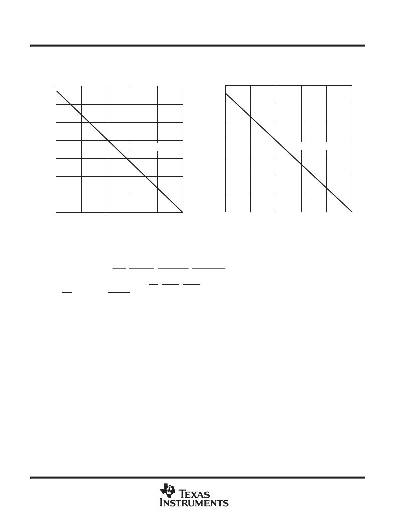
400
200
1200
025
50
75
100
800
600
1000
MAXIMUM CONTINUOUS POWER DISSIPATION
vs
FREE-AIR TEMPERATURE
1400
125
150
TA – Free-Air Temperature –
°
C
Figure 2
R
θ
JA = 93
°
C/W
–
PD
2000
1000
6000
025
50
75
100
–
PD
4000
3000
5000
MAXIMUM CONTINUOUS POWER DISSIPATION
vs
CASE TEMPERATURE
7000
125
150
TA – Case Temperature –
°
C
Figure 3
R
θ
JC = 19
°
C/W
absolute maximum ratings over operating free-air temperature range (unless otherwise noted)
Supply voltage range, V
CC
, VCP
. . . . . . . . . . . . . . . . . . . . . . . . . . . . . . . . . . . . . . . . . . . . . . . . . . . .
Input voltage range at OFF, MIC_EN, SPKR_EN, RNGR_EN, SPKR_IN,
RNGR_IN, MIC_IN+, MIC_IN–
. . . . . . . . . . . . . . . . . . . . . . . . . . . . . . . . . . . . . . . . . . . . . . . . . .
Input voltage range at PL, PA, PB, EN, EN_A, EN_B,
ON, ON_REM, EN_CP
. . . . . . . . . . . . . . . . . . . . . . . . . . . . . . . . . . . . . . . . . . . . . . . . . . . . . . .
Continuous total power dissipation
. . . . . . . . . . . . . . . . . . . . . . . . . . . . . . . . . . . . . . .
Peak output current
. . . . . . . . . . . . . . . . . . . . . . . . . . . . . . . . . . . . . . . . . . . . . . . . . . . . . . . . . . . . . .
Output current range at SPKR_OUT+, SPKR_OUT–,
RNGR_OUT+, RNGR_OUT–
. . . . . . . . . . . . . . . . . . . . . . . . . . . . . . . . . . . . . . . . . . . . .
Power dissipation
. . . . . . . . . . . . . . . . . . . . . . . . . . . . . . . . . . . . . . . . . . . . . . . . . . . . . .
Operating free-air temperature range, T
A
. . . . . . . . . . . . . . . . . . . . . . . . . . . . . . . . . . . . . . . . . . . .
Storage temperature range, T
stg
. . . . . . . . . . . . . . . . . . . . . . . . . . . . . . . . . . . . . . . . . . . . . . . . . . .
Lead Temperature 1,6 mm (1/16 inch) from case for 10 seconds
–0.3 V to 12 V
–0.3 V to 7 V
–0.3 V to V
CC
See dissipation rating table
Internally limited
–100 mA to 100 mA
See dissipation rating table
–40
°
C to 85
°
C
–65
°
C to 150
°
C
260
°
C
. . . . . . . . . . . . . . . . . . . . . . . . . . . . . . .
Stresses beyond those listed under “absolute maximum ratings” may cause permanent damage to the device. These are stress ratings only, and
functional operation of the device at these or any other conditions beyond those indicated under “recommended operating conditions” is not
implied. Exposure to absolute-maximum-rated conditions for extended periods may affect device reliability.
All voltages are with respect to GND.
相關(guān)PDF資料 |
PDF描述 |
|---|---|
| TPS9104Y | CELLULAR SUBSCRIBER TERMINAL POWER SUPPLY/AUDIO SYSTEM |
| TPS9125PW | 5 V/3 V SIM SUPPLY AND LEVEL SHIFTERS |
| TPV375 | 14 pin DIP, 5.0 Volt, HCMOS/TTL, Clock Oscillator |
| TPV376 | 14 pin DIP, 5.0 Volt, HCMOS/TTL, Clock Oscillator |
| TPV385 | 14 pin DIP, 5.0 Volt, HCMOS/TTL, Clock Oscillator |
相關(guān)代理商/技術(shù)參數(shù) |
參數(shù)描述 |
|---|---|
| TPS9104Y | 制造商:TI 制造商全稱:Texas Instruments 功能描述:CELLULAR SUBSCRIBER TERMINAL POWER SUPPLY/AUDIO SYSTEM |
| TPS9110 | 制造商:未知廠家 制造商全稱:未知廠家 功能描述:Cellular Subscriber Terminal Power Supply |
| TPS9110IPWLE | 制造商:TI 制造商全稱:Texas Instruments 功能描述:CELLULAR SUBSCRIBER TERMINAL POWER SUPPLY |
| TPS9110IPWR | 制造商:Rochester Electronics LLC 功能描述:- Bulk |
| TPS9111 | 制造商:未知廠家 制造商全稱:未知廠家 功能描述:Cellular Subscriber Terminal Power Supply |
發(fā)布緊急采購,3分鐘左右您將得到回復(fù)。