- 您現(xiàn)在的位置:買賣IC網(wǎng) > PDF目錄382648 > TMX320F2810PBKAEP (Texas Instruments, Inc.) Digital Signal Processors PDF資料下載
參數(shù)資料
| 型號(hào): | TMX320F2810PBKAEP |
| 廠商: | Texas Instruments, Inc. |
| 元件分類: | 數(shù)字信號(hào)處理 |
| 英文描述: | Digital Signal Processors |
| 中文描述: | 數(shù)字信號(hào)處理器 |
| 文件頁數(shù): | 13/103頁 |
| 文件大?。?/td> | 1341K |
| 代理商: | TMX320F2810PBKAEP |
第1頁第2頁第3頁第4頁第5頁第6頁第7頁第8頁第9頁第10頁第11頁第12頁當(dāng)前第13頁第14頁第15頁第16頁第17頁第18頁第19頁第20頁第21頁第22頁第23頁第24頁第25頁第26頁第27頁第28頁第29頁第30頁第31頁第32頁第33頁第34頁第35頁第36頁第37頁第38頁第39頁第40頁第41頁第42頁第43頁第44頁第45頁第46頁第47頁第48頁第49頁第50頁第51頁第52頁第53頁第54頁第55頁第56頁第57頁第58頁第59頁第60頁第61頁第62頁第63頁第64頁第65頁第66頁第67頁第68頁第69頁第70頁第71頁第72頁第73頁第74頁第75頁第76頁第77頁第78頁第79頁第80頁第81頁第82頁第83頁第84頁第85頁第86頁第87頁第88頁第89頁第90頁第91頁第92頁第93頁第94頁第95頁第96頁第97頁第98頁第99頁第100頁第101頁第102頁第103頁

TMS320F2810, TMS320F2812
DIGITAL SIGNAL PROCESSORS
SPRS174B
–
APRIL 2001
–
REVISED SEPTEMBER 2001
13
POST OFFICE BOX 1443
HOUSTON, TEXAS 77251
–
1443
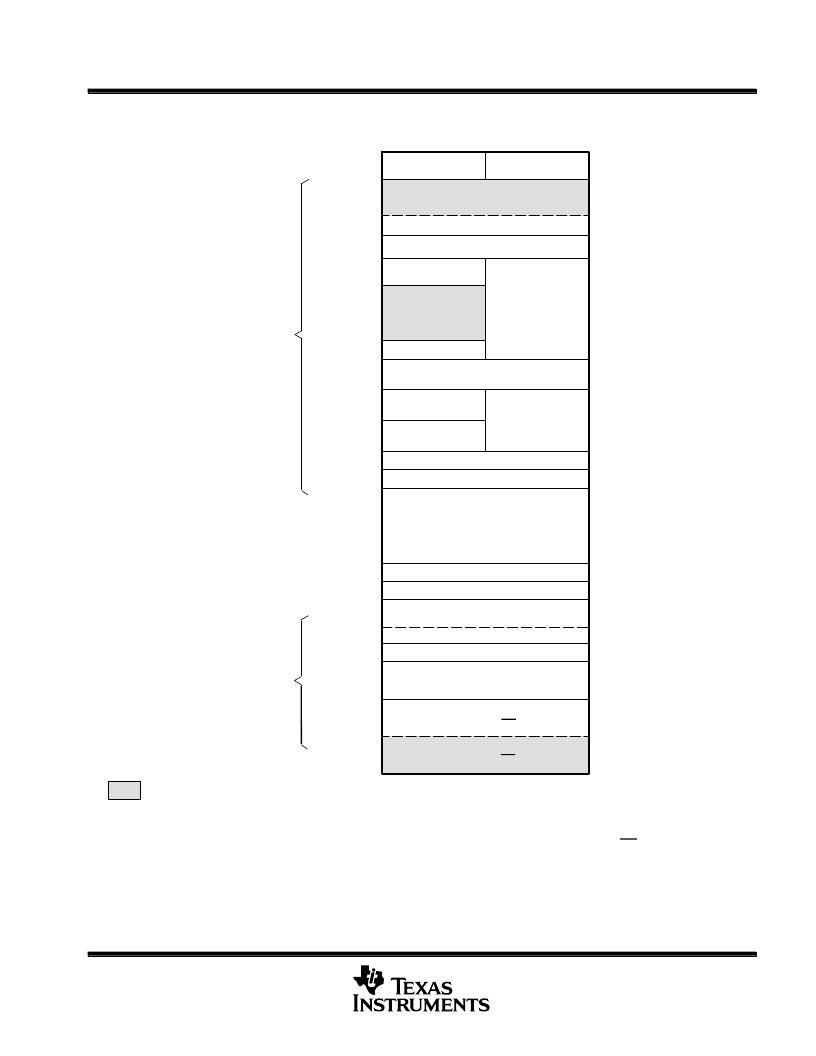
memory map (continued)
Block
Start Address
L
(
0x0000
–
0000
M0 Vector
–
RAM (32
×
32)
(enabled if VMAP = 0)
Data Space
Prog Space
M0 SARAM (1K
×
16)
M1 SARAM (1K
×
16)
Peripheral Frame 0
(2K
×
16)
PIE Vector - RAM
(256
×
16)
(enabled if VMAP = 0,
ENPIE = 1)
0x0000
–
0040
0x0000
–
0400
0x0000
–
0800
Reserved
Reserved
Reserved
L0 SARAM (4K
×
16, Secure Block)
Peripheral Frame 2
(4K
×
16, Protected)
Reserved
Peripheral Frame 1
(4K
×
16, Protected)
L1 SARAM (4K
×
16, Secure Block)
Reserved
Reserved
FLASH (64K
×
16, Secure Block)
128-Bit Password
H0 SARAM (8K
×
16)
Reserved
Boot ROM (4K
×
16)
(enabled if MP/MC = 0)
BROM Vector - ROM (32
×
32)
(enabled if VMAP = 1, MP/MC = 0, ENPIE = 0)
0x0000
–
0D00
0x0000
–
1000
0x0000
–
2000
0x0000
–
6000
0x0000
–
7000
0x0000
–
8000
0x0000
–
9000
0x0000
–
A000
0x003D
–
8000
0x003E
–
0000
0x003F
–
0000
0x003F
–
7FF8
0x003F
–
8000
0x003F
–
A000
0x003F
–
F000
0x003F
–
FFC0
H
(
P
On-Chip Memory
Only one of these vector maps
—
M0 vector, PIE vector, BROM vector
—
should be enabled at a time.
LEGEND:
OTP (2K
×
16, Secure Block)
0x003D
–
7800
NOTES: A. Memory blocks are not to scale. Flash location subject to change.
B. Reserved locations are reserved for future expansion. Application should not access these areas.
C. Boot ROM and Zone 7 memory maps are active either in on-chip or XINTF zone depending on MP/MC, not in both.
D. Peripheral Frame 0, Peripheral Frame 1, and Peripheral Frame 2 memory maps are restricted to data memory only. User program
cannot access these memory maps in program space.
E.
“
Protected
”
means the order of Write followed by Read operations is preserved rather than the pipeline order.
F. Certain memory ranges are EALLOW protected for spurious writes after configuration.
G. Zone 6 and Zone 7 share the same chip select; hence, these memory blocks have mirrored locations.
Figure 2. F2810 Memory Map
P
相關(guān)PDF資料 |
PDF描述 |
|---|---|
| TMP320F2810PBKAEP | Digital Signal Processors |
| TMX320F2810PBKS | DIGITAL SIGNAL PROCESSORS |
| TMP320F2810PBKS | DIGITAL SIGNAL PROCESSORS |
| TMP320F2810GHHA | DIGITAL SIGNAL PROCESSORS |
| TMX320F2810GHHMEP | Digital Signal Processors |
相關(guān)代理商/技術(shù)參數(shù) |
參數(shù)描述 |
|---|---|
| TMX320F2810PBKS | 制造商:TI 制造商全稱:Texas Instruments 功能描述:DIGITAL SIGNAL PROCESSORS |
| TMX320F2810PGFA | 制造商:TI 制造商全稱:Texas Instruments 功能描述:DIGITAL SIGNAL PROCESSORS |
| TMX320F2810PGFAEP | 制造商:TI 制造商全稱:Texas Instruments 功能描述:Digital Signal Processors |
| TMX320F2810PGFS | 制造商:TI 制造商全稱:Texas Instruments 功能描述:DIGITAL SIGNAL PROCESSORS |
| TMX320F2811GHHA | 制造商:TI 制造商全稱:Texas Instruments 功能描述:TMS320R2811, TMS320R2812 Digital Signal Processors |
發(fā)布緊急采購,3分鐘左右您將得到回復(fù)。