- 您現(xiàn)在的位置:買賣IC網(wǎng) > PDF目錄384013 > TMC2249AKEC1 (FAIRCHILD SEMICONDUCTOR CORP) JT 18C 18#20 PIN GRND PLUG PDF資料下載
參數(shù)資料
| 型號: | TMC2249AKEC1 |
| 廠商: | FAIRCHILD SEMICONDUCTOR CORP |
| 元件分類: | 數(shù)字信號處理外設(shè) |
| 英文描述: | JT 18C 18#20 PIN GRND PLUG |
| 中文描述: | 12-BIT, DSP-MIXER, PQFP120 |
| 封裝: | METRIC, QFP-120 |
| 文件頁數(shù): | 6/18頁 |
| 文件大小: | 138K |
| 代理商: | TMC2249AKEC1 |
PRODUCT SPECIFICATION
TMC2249A
6
REV. 1.0.2 7/6/00
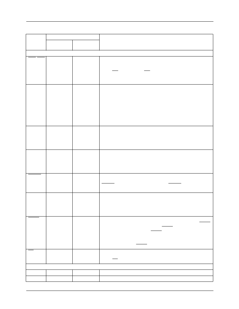
Controls
ENA-END N13, N2, C12,
A3
60, 33, 89, 116
Input Enables.
are latched into delay pipeline i, and data already in pipeline i
advance by one register position, on each rising edge of CLK for
which ENi is LOW. When ENi is HIGH, the data in pipeline i do not
move and the value at the input port i will be lost before it reaches
the multiplier.
Negate.
The products of the multipliers are negated causing a
subtraction to be performed during the internal summation of
products, when the NEGate controls are HIGH, NEG1 negates the
product A x B, while NEG2 acts on the output of the multiplier which
generates the product C x D. When the length controls ADEL–
DDEL are set to zero, these controls indicate the operation to be
performed on data input during the same clock. As nonzero values
for ADEL–DDEL do not affect the pipelining of these controls, their
effect is not synchronous with the data input in these cases.
Round.
When the rounding control is HIGH, the 24-bit sum of
products resulting from data input during that clock is rounded to 16
bits. When enabled rounding is automatically performed only during
the first cycle of each accumulation sequence, to avoid the
accumulation of roundoff errors.
Feedthrough.
When the Feedthrough control is HIGH, the pipeline
delay through the cascade data path is minimized to simplify the
cascading of multiple devices. When FT is LOW and ADEL through
DDEL are all set to 0, the data inputs are aligned, such that
S(n+6) = CAS(n) + A(n)B(n) + C(n)D(n). See Table 2.
Cascade Enable.
Data presented at the cascade data input port
are latched and accumulated internally when the input enable
CASEN during that clock is LOW. When CASEN is HIGH, the
cascade input port is ignored.
Accumulate.
When the registered ACCumulator control is LOW, no
internal accumulation will be performed on the data input during the
current clock, effectively clearing the prior accumulated sum. When
ACC is HIGH, the internal accumulator adds the emerging product
to the sum of the previous products and RND is disabled.
Swap Output Words.
The user may access both the most and
least-significant 16 bits of the 24-bit accumulator by utilizing SWAP.
Normal operation of the device, with SWAP = HIGH, outputs the
most significant word. Setting SWAP = LOW puts a double-register
structure into "toggle" mode, allowing the user to examine the LSW
on alternate clocks. New output data will not be clocked into the
output registers until SWAP returns HIGH.
Output Enable.
Data currently in the output registers is available at
the output bus S
15-0
when the asynchronous Output Enable is LOW.
When OE is HIGH, the outputs are in the high-impedance state.
Input data presented to port i11-0 (i=A,B,C, or D)
NEG1,2
B1, D3
3, 4
RND
C2
5
FT
E11
84
CASEN
D13
83
ACC
B2
2
SWAP
K3
28
OE
M1
27
No Connect
L12
D4
65
Do Not Connect
Index Pin (optional)
Pin Descriptions
(continued)
Pin Name
Pin Number
Pin Function Description
CPGA/PPGA/
MPGA
MQFP
相關(guān)PDF資料 |
PDF描述 |
|---|---|
| TMC2249AKEC2 | Digital Mixer 12 x 12 Bit, 60 MHz |
| TMC2249AH5C | Digital Mixer 12 x 12 Bit, 60 MHz |
| TMC2249AH5C1 | Digital Mixer 12 x 12 Bit, 60 MHz |
| TMC2249AH5C2 | Digital Mixer 12 x 12 Bit, 60 MHz |
| TMC2250AH5C | Matrix Multiplier 12 x 10 bit, 50 MHz |
相關(guān)代理商/技術(shù)參數(shù) |
參數(shù)描述 |
|---|---|
| TMC2249AKEC2 | 功能描述:視頻 IC Digital Mixer RoHS:否 制造商:Fairchild Semiconductor 工作電源電壓:5 V 電源電流:80 mA 最大工作溫度:+ 85 C 封裝 / 箱體:TSSOP-28 封裝:Reel |
| TMC2250/TMC2272 WAF | 制造商:Fairchild Semiconductor Corporation 功能描述: |
| TMC2250A | 制造商:FAIRCHILD 制造商全稱:Fairchild Semiconductor 功能描述:Matrix Multiplier 12 x 10 bit, 50 MHz |
| TMC2250AG1C | 制造商:CADEKA 制造商全稱:CADEKA 功能描述:Matrix Multiplier 12 x 10 bit, 50 MHz |
| TMC2250AG1C2 | 制造商:CADEKA 制造商全稱:CADEKA 功能描述:Matrix Multiplier 12 x 10 bit, 50 MHz |
發(fā)布緊急采購,3分鐘左右您將得到回復(fù)。