- 您現(xiàn)在的位置:買(mǎi)賣(mài)IC網(wǎng) > PDF目錄98253 > TLV320AIC27CPFB (TEXAS INSTRUMENTS INC) SPECIALTY CONSUMER CIRCUIT, PQFP48 PDF資料下載
參數(shù)資料
| 型號(hào): | TLV320AIC27CPFB |
| 廠商: | TEXAS INSTRUMENTS INC |
| 元件分類(lèi): | 消費(fèi)家電 |
| 英文描述: | SPECIALTY CONSUMER CIRCUIT, PQFP48 |
| 封裝: | PLASTIC, TQFP-48 |
| 文件頁(yè)數(shù): | 36/54頁(yè) |
| 文件大小: | 732K |
| 代理商: | TLV320AIC27CPFB |
第1頁(yè)第2頁(yè)第3頁(yè)第4頁(yè)第5頁(yè)第6頁(yè)第7頁(yè)第8頁(yè)第9頁(yè)第10頁(yè)第11頁(yè)第12頁(yè)第13頁(yè)第14頁(yè)第15頁(yè)第16頁(yè)第17頁(yè)第18頁(yè)第19頁(yè)第20頁(yè)第21頁(yè)第22頁(yè)第23頁(yè)第24頁(yè)第25頁(yè)第26頁(yè)第27頁(yè)第28頁(yè)第29頁(yè)第30頁(yè)第31頁(yè)第32頁(yè)第33頁(yè)第34頁(yè)第35頁(yè)當(dāng)前第36頁(yè)第37頁(yè)第38頁(yè)第39頁(yè)第40頁(yè)第41頁(yè)第42頁(yè)第43頁(yè)第44頁(yè)第45頁(yè)第46頁(yè)第47頁(yè)第48頁(yè)第49頁(yè)第50頁(yè)第51頁(yè)第52頁(yè)第53頁(yè)第54頁(yè)
TLV320AIC27
STEREO AUDIO CODEC
SLAS253A – MARCH 2000 – REVISED SEPTEMBER 2000
41
POST OFFICE BOX 655303
DALLAS, TEXAS 75265
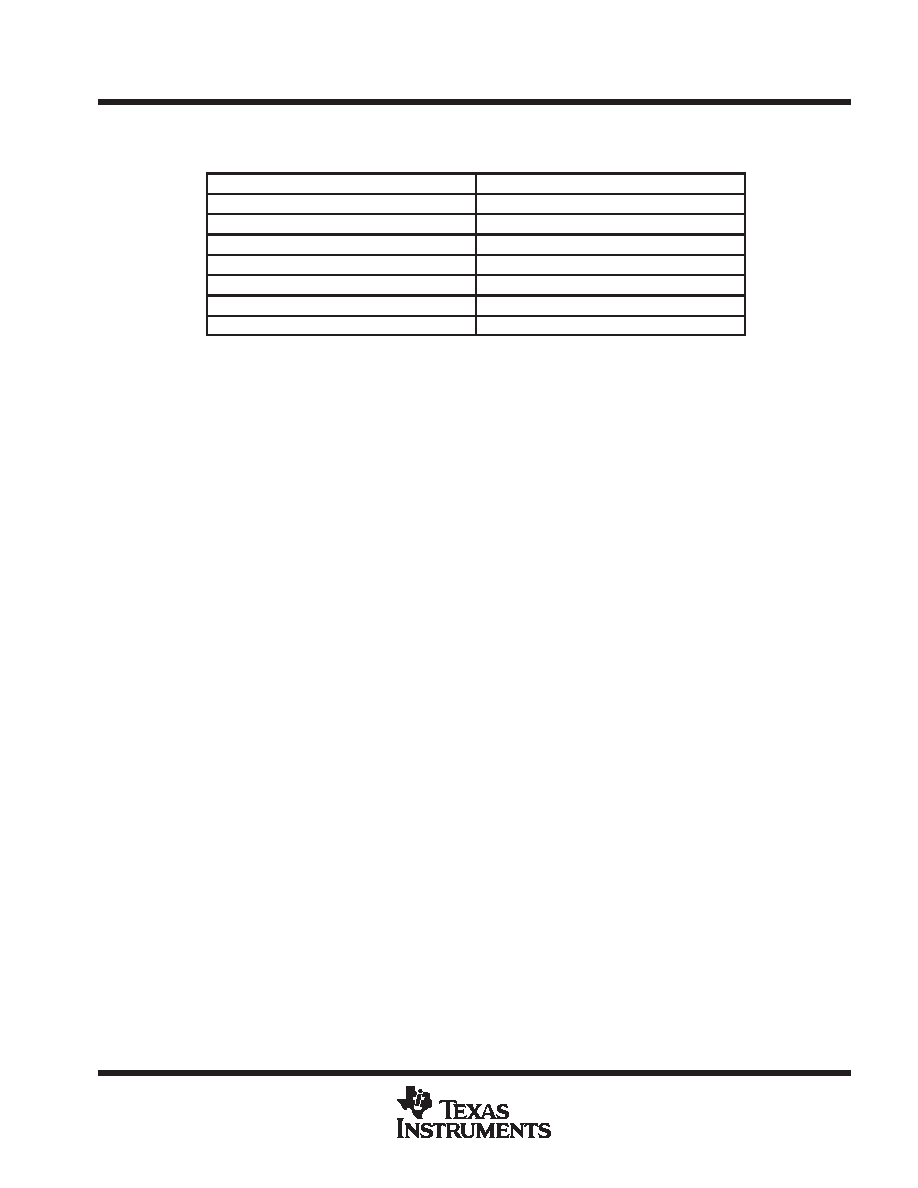
GPIO pins and I2S (continued)
Table 22. Connection to External I2S DACs
TLV320AIC27 CONNECTION
I2S DAC CONNECTION
BITCLK
SCLK
BITCLK
BLCK
Pin 48 – GPIO3
LRCLK
Pin 43 – GPIO1 (LFE/center data in ID00)
SDATA on external DAC
Pin 44 – GPIO2 (surround data in ID00)
SDATA on other external DAC
FORMAT pin – connect for I2S mode
DEEMPH (if provided) – disable
Configuration of these pins as GPIO is explained in the control interface description.
modem mode
In modem mode, the modem Tx data is mapped onto the rear DACs. Rear DAC sample rates are set by the
modem’s Tx sample rate register 40h. Extended modem capability register 3Ch indicates that line1 is
supported.
modem mode features
D Vendor ID reads back TXN4
D Headphone channel flagged as not supported (bit ID4 in register 00h)
D Four channels of DAC and two of ADC conversion available, with all recommended audio and modem
sample rates supported via the audio sample rate registers 2Ch (front DACs), 40h (rear DACs), and 32h
(ADCs in audio mode).
D ADC samples are outputted onto both audio slots 3 and 4 and also onto line2/1 slots 10 and 5, respectively.
D Line1 Tx modem data is mapped onto the rear DACs as data and as inverted data, so that the pair of rear
DACs produce a differential Tx modem data output.
D Right audio ADC changes to use line1 sample rate 40h when input mix selects PHONE as its IP.
D The additional vendor-specific mode DLM is available via bit DLM in register 5Ah. Setting this bit provides
support for line2 as well as line1 slots. Rear DACs are mapped onto line1 and line2 Tx modem data slots,
and ADC left and right outputs are mapped both onto normal audio slots 3 and 4 and also onto the line1
and line2 Rx modem data slots. Modem rate register 40h is used for both DACs, and the ADC’s use their
normal sample rate registers (that is, audio registers), unless right channel is selected as PHONE, in which
case they too use register 40h.
D If DLM bit is set in register 5Ah, then line1 Tx data is mapped onto the rear left DAC, and Line2 Tx data is
mapped onto the rear right DAC. Both rear DACs use the same sample rate from register 40h (if 42h is
written to, 40h will be updated instead).
D The left ADC always uses the normal ADC audio rate register, except when RPHONE is selected in DLM
mode, in which case it uses 40h.
D GPIO capability supporting GPIO (11 to 13) flagged as supported
D Master/slave ID0/1 supported, with automatic remapping of the rear or LFE/center DAC slot data onto the
front DACs when ID 10 or 11 is selected.
D Headphone/line level output pins 39 and 41 used to output the rear DAC signals, with volume controlled
from register 04h. Rear mixer PGA is fixed in mute condition.
D 3D-stereo enhancement supported
相關(guān)PDF資料 |
PDF描述 |
|---|---|
| TLV320AIC27IPFB | SPECIALTY CONSUMER CIRCUIT, PQFP48 |
| TLV320AIC27TPFB | SPECIALTY CONSUMER CIRCUIT, PQFP48 |
| TLV320AIC28IRGZR | SPECIALTY CONSUMER CIRCUIT, PQCC48 |
| TLV320AIC28IRGZ | SPECIALTY CONSUMER CIRCUIT, PQCC48 |
| TLV320AIC28IRGZRG4 | SPECIALTY CONSUMER CIRCUIT, PQCC48 |
相關(guān)代理商/技術(shù)參數(shù) |
參數(shù)描述 |
|---|---|
| TLV320AIC27IPFB | 制造商:TI 制造商全稱:Texas Instruments 功能描述:STEREO AUDIO CODEC |
| TLV320AIC27PFB | 制造商:TI 制造商全稱:Texas Instruments 功能描述:STEREO AUDIO CODEC |
| TLV320AIC27TPFB | 制造商:Rochester Electronics LLC 功能描述:- Bulk 制造商:Texas Instruments 功能描述: |
| TLV320AIC28 | 制造商:TI 制造商全稱:Texas Instruments 功能描述:STEREO AUDIO CODEC WITH INTERGRATED HEADPHONE AND SPEAKER AMPLIFIERS |
| TLV320AIC28_08 | 制造商:TI 制造商全稱:Texas Instruments 功能描述:STEREO AUDIO CODEC WITH INTEGRATED HEADPHONE AND SPEAKER AMPLIFIERS |
發(fā)布緊急采購(gòu),3分鐘左右您將得到回復(fù)。