- 您現(xiàn)在的位置:買賣IC網(wǎng) > PDF目錄383952 > TL750M12Y (Texas Instruments, Inc.) LOW-DROPOUT VOLTAGE REGULATORS PDF資料下載
參數(shù)資料
| 型號: | TL750M12Y |
| 廠商: | Texas Instruments, Inc. |
| 元件分類: | 基準電壓源/電流源 |
| 英文描述: | LOW-DROPOUT VOLTAGE REGULATORS |
| 中文描述: | 低壓差電壓調(diào)節(jié)器 |
| 文件頁數(shù): | 3/12頁 |
| 文件大小: | 169K |
| 代理商: | TL750M12Y |
TL750M TL751MSERIES
LOW-DROPOUT VOLTAGE REGULATORS
SLVS021H – JANUARY 1988 – REVISED JANUARY 2000
3
POST OFFICE BOX 655303
DALLAS, TEXAS 75265
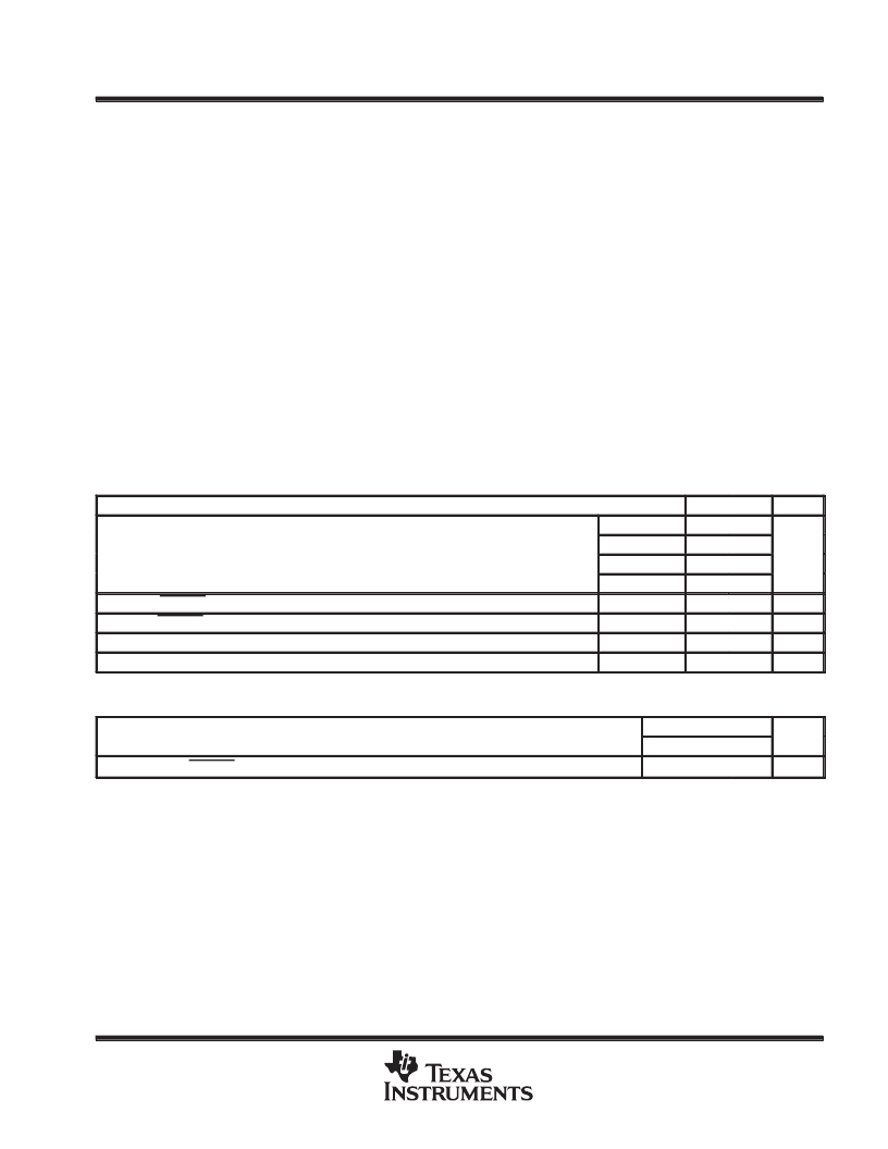
absolute maximum ratings over virtual junction temperature range (unless otherwise noted)
Continuous input voltage
Transient input voltage (see Figure 3)
Continuous reverse input voltage
Transient reverse input voltage: t = 100 ms
Package thermal impedance,
θ
JA
(see Notes 1 and 2): KC package
26 V
60 V
–15 V
–50 V
22
°
C/W
23
°
C/W
23
°
C/W
28
°
C/W
. . . . . . . . . . . . . . . . . . . . . . . . . . . . . . . . . . . . . . . . . . . . . . . . . . . . . . . . . . . . . . . . . . . .
. . . . . . . . . . . . . . . . . . . . . . . . . . . . . . . . . . . . . . . . . . . . . . . . . . . . . . . .
. . . . . . . . . . . . . . . . . . . . . . . . . . . . . . . . . . . . . . . . . . . . . . . . . . . . . . . . . . .
. . . . . . . . . . . . . . . . . . . . . . . . . . . . . . . . . . . . . . . . . . . . . . . . . . .
. . . . . . . . . . . . . . . . . . . . . . . . . . .
KTE package
. . . . . . . . . . . . . . . . . . . . . . . . .
KTG package
. . . . . . . . . . . . . . . . . . . . . . . . .
KTP package
. . . . . . . . . . . . . . . . . . . . . . . . .
. . . . . . . . . . . . . . . . . . . . . . . . . . . . . . . . . . . . . . . . . . . . . . . .
. . . . . . . . . . . . . . . . . . . . . . . . . . . . . . .
. . . . . . . . . . . . . . . . . . . . . . . . . . . . . . . . . . . . . . . . . . . . . . . . . . .
Virtual junction temperature range, T
J
Lead temperature 1,6 mm (1/16 inch) from case for 10 seconds
Storage temperature range, T
stg
Stresses beyond those listed under “absolute maximum ratings” may cause permanent damage to the device. These are stress ratings only, and
functional operation of the device at these or any other conditions beyond those indicated under “recommended operating conditions” is not
implied. Exposure to absolute-maximum-rated conditions for extended periods may affect device reliability.
NOTES:
1. Maximum power dissipation is a function of TJ(max),
θ
JA, and TA. The maximum allowable power dissipation at any allowable
ambient temperature is PD = (TJ(max) – TA)/
θ
JA. Operating at the absolute maximum TJ of 150
°
C can impact reliability. Due to
variation in individual device electrical characteristics and thermal resistance, the built-in thermal overload protection may be
activated at power levels slightly above or below the rated dissipation.
2. The package thermal impedance is calculated in accordance with JESD 51.
0
°
C to 150
°
C
260
°
C
–65
°
C to 150
°
C
recommended operating conditions
MIN
MAX
UNIT
TL75xM05
6
26
Input voltage range VI
Input voltage range, VI
TL75xM08
9
26
V
TL75xM10
11
26
TL75xM12
13
26
High-level ENABLE input voltage, VIH
Low-level ENABLE input voltage, VIL
Output current range, IO
Operating virtual junction temperature range, TJ
TL751Mxx
2
15
V
TL751Mxx
0
0.8
V
TL75xMxxC
750
mA
°
C
TL75xMxxC
0
125
electrical characteristics, V
I
= 14 V, I
O
= 300 mA, T
J
= 25
°
C
PARAMETER
TL751MXXX
MIN
UNIT
TYP
MAX
Response time, ENABLE to output
50
μ
s
相關PDF資料 |
PDF描述 |
|---|---|
| TL751M | LOW-DROPOUT VOLTAGE REGULATORS |
| TL751M05CKTG | LOW-DROPOUT VOLTAGE REGULATORS |
| TL751M08CKTG | LOW-DROPOUT VOLTAGE REGULATORS |
| TL7757D | SUPPLY-VOLTAGE SUPERVISOR AND PRECISION VOLTAGE DETECTOR |
| TL7757LP | SUPPLY-VOLTAGE SUPERVISOR AND PRECISION VOLTAGE DETECTOR |
相關代理商/技術參數(shù) |
參數(shù)描述 |
|---|---|
| TL750M-Q1 | 制造商:TI 制造商全稱:Texas Instruments 功能描述:AUTOMOTIVE LOW-DROPOUT VOLTAGE REGULATORS |
| TL75-1 | 制造商:Fluke Electronics 功能描述:LEAD SET 70/20 FLUKE TL75 制造商:Fluke Electronics 功能描述:LEAD SET, 70/20, FLUKE TL75 |
| TL75150CD | 制造商:Texas Instruments 功能描述:75150CD |
| TL751L | 制造商:TI 制造商全稱:Texas Instruments 功能描述:LOW-DROPOUT VOLTAGE REGULATORS |
| TL751L05CD | 功能描述:低壓差穩(wěn)壓器 - LDO 5V 150mA LDO RoHS:否 制造商:Texas Instruments 最大輸入電壓:36 V 輸出電壓:1.4 V to 20.5 V 回動電壓(最大值):307 mV 輸出電流:1 A 負載調(diào)節(jié):0.3 % 輸出端數(shù)量: 輸出類型:Fixed 最大工作溫度:+ 125 C 安裝風格:SMD/SMT 封裝 / 箱體:VQFN-20 |
發(fā)布緊急采購,3分鐘左右您將得到回復。