- 您現(xiàn)在的位置:買賣IC網(wǎng) > PDF目錄383949 > TL16C550BIN (Texas Instruments, Inc.) ASYNCHRONOUS COMMUNICATIONS ELEMENT PDF資料下載
參數(shù)資料
| 型號: | TL16C550BIN |
| 廠商: | Texas Instruments, Inc. |
| 英文描述: | ASYNCHRONOUS COMMUNICATIONS ELEMENT |
| 中文描述: | 異步通信元 |
| 文件頁數(shù): | 7/35頁 |
| 文件大小: | 499K |
| 代理商: | TL16C550BIN |
第1頁第2頁第3頁第4頁第5頁第6頁當(dāng)前第7頁第8頁第9頁第10頁第11頁第12頁第13頁第14頁第15頁第16頁第17頁第18頁第19頁第20頁第21頁第22頁第23頁第24頁第25頁第26頁第27頁第28頁第29頁第30頁第31頁第32頁第33頁第34頁第35頁
TL16C550B, TL16C550BI
ASYNCHRONOUS COMMUNICATIONS ELEMENT
SLLS136B – JANUARY 1994 – REVISED AUGUST 1996
7
POST OFFICE BOX 655303
DALLAS, TEXAS 75265
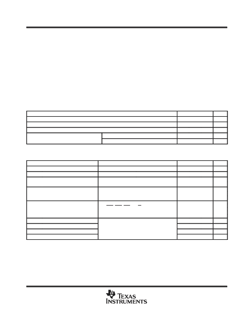
absolute maximum ratings over operating free-air temperature range (unless otherwise noted)
Supply voltage range, V
CC
(see Note 1)
Input voltage range at any input, V
I
Output voltage range, V
O
Continuous total power dissipation at (or below) 70
°
C
Storage temperature range, T
stg
Operating free-air temperature range, T
A
: TL16C550B
–0.5 V to 7 V
–0.5 V to 7 V
–0.5 V to 7 V
300 mW
–65
°
C to 150
°
C
0
°
C to 70
°
C
–40
°
C to 85
°
C
. . . . . . . . . . . . . . . . . . . . . . . . . . . . . . . . . . . . . . . . . . . . . .
. . . . . . . . . . . . . . . . . . . . . . . . . . . . . . . . . . . . . . . . . . . . . . . . . . .
. . . . . . . . . . . . . . . . . . . . . . . . . . . . . . . . . . . . . . . . . . . . . . . . . . . . . . . . . . .
. . . . . . . . . . . . . . . . . . . . . . . . . . . . . . . . . . . . . . .
. . . . . . . . . . . . . . . . . . . . . . . . . . . . . . . . . . . . . . . . . . . . . . . . . . .
. . . . . . . . . . . . . . . . . . . . . . . . . . . . . . . . . .
TL16C550BI
. . . . . . . . . . . . . . . . . . . . . . . . . . . . . . .
Case temperature for 10 seconds, T
C
: FN package
Lead temperature 1,6 mm (1/16 inch) from case for 10 seconds: N or PT package
260
°
C
260
°
C
. . . . . . . . . . . . . . . . . . . . . . . . . . . . . . . . . . . . . . . . . .
. . . . . . . . . . . . . . .
Stresses beyond those listed under “absolute maximum ratings” may cause permanent damage to the device. These are stress ratings only and
functional operation of the device at these or any other conditions beyond those indicated under “recommended operating conditions” is not
implied. Exposure to absolute-maximum-rated conditions for extended periods may affect device reliability.
NOTE 1: All voltage values are with respect to VSS (ground).
recommended operating conditions
MIN
NOM
MAX
UNIT
Supply voltage, VCC
High-level input voltage, VIH
Low-level input voltage, VIL
4.75
5
5.25
V
2
VCC
0.8
70
V
–0.5
V
°
C
°
C
Operating free-air temperature TA
O erating free-air tem erature, TA
TL16C550B
0
TL16C550BI
–40
85
electrical characteristics over recommended ranges of supply voltage and operating free-air
temperature (unless otherwise noted)
PARAMETER
TEST CONDITIONS
MIN
TYP
MAX
UNIT
VOH
VOL
High-level output voltage
IOH = –1 mA
IOL = 1.6 mA
VCC = 5.25 V,
VI = 0 to 5.25 V,
VCC = 5.25 V,
VCC 5.25 V,
VO = 0 to 5.25 V,
Chip selected in write mode or chip deselect
2.4
V
Low-level output voltage
0.4
V
Il
Input current
VSS = 0,
All other terminals floating
10
μ
A
VSS = 0,
VSS 0,
IOZ
High-impedance-state output current
±
20
A
μ
VCC= 5 25 V
SIN DSR DCD CTS and RI at 2 V
SIN, DSR, DCD, CTS, and RI at 2 V,
All other inputs at 0 8 V
All other inputs at 0.8 V,
N l
No load on outputs,
°
C
TA= 25
ICC
Supply current
XTAL1 at 4 MHz,
Baud rate = 50 kbit/s
10
mA
Ci(CLK)
Co(CLK)
Ci
Co
All typical values are at VCC = 5 V, TA = 25
°
C.
These parameters apply for all outputs except XOUT.
Clock input capacitance
15
20
pF
Clock output capacitance
VCC = 0,
f = 1 MHz,
All other terminals grounded
VSS = 0,
TA= 25
TA = 25
°
C,
20
30
pF
Input capacitance
Output capacitance
6
10
20
pF
pF
10
相關(guān)PDF資料 |
PDF描述 |
|---|---|
| TL16C550CIN | ASYNCHRONOUS COMMUNICATIONS ELEMENT WITH AUTOFLOW CONTROL |
| TL16C550CIPFB | ASYNCHRONOUS COMMUNICATIONS ELEMENT WITH AUTOFLOW CONTROL |
| TL16C552AMPN | DUAL ASYNCHRONOUS COMMUNICATIONS ELEMENT WITH FIFO |
| TL16C552AHV | DUAL ASYNCHRONOUS COMMUNICATIONS ELEMENT WITH FIFO |
| TL16C552AMFN | DUAL ASYNCHRONOUS COMMUNICATIONS ELEMENT WITH FIFO |
相關(guān)代理商/技術(shù)參數(shù) |
參數(shù)描述 |
|---|---|
| TL16C550BIPT | 制造商:TI 制造商全稱:Texas Instruments 功能描述:ASYNCHRONOUS COMMUNICATIONS ELEMENT |
| TL16C550BN | 制造商:Rochester Electronics LLC 功能描述:- Bulk |
| TL16C550BPT | 制造商:Rochester Electronics LLC 功能描述:- Tape and Reel |
| TL16C550BPTR | 制造商:Rochester Electronics LLC 功能描述:- Tape and Reel |
| TL16C550C | 制造商:TI 制造商全稱:Texas Instruments 功能描述:操作和TA550CI應(yīng)該一樣,不妨試試 |
發(fā)布緊急采購,3分鐘左右您將得到回復(fù)。