- 您現(xiàn)在的位置:買賣IC網(wǎng) > PDF目錄361483 > TK15328M (TOKO Inc.) Audio Analog Switch PDF資料下載
參數(shù)資料
| 型號: | TK15328M |
| 廠商: | TOKO Inc. |
| 英文描述: | Audio Analog Switch |
| 中文描述: | 音頻模擬開關(guān) |
| 文件頁數(shù): | 2/12頁 |
| 文件大小: | 213K |
| 代理商: | TK15328M |
Page 2
June 1999 TOKO, Inc.
TK15328
L
O
B
M
Y
S
R
E
T
E
M
A
R
A
P
S
N
O
I
D
N
O
C
T
S
E
T
N
I
M
P
Y
T
X
A
M
S
T
N
U
I
C
C
t
e
C
y
p
u
S
2
2
A
m
N
O
I
C
E
S
L
O
R
T
N
O
C
Y
E
K
V
L
l
v
e
L
w
o
L
e
g
a
V
t
p
n
1
e
N
3
8
+
V
V
H
I
l
v
e
L
h
g
H
e
g
a
V
t
p
n
8
V
C
C
3
+
V
Z
N
I
e
c
n
a
d
e
p
m
I
p
n
0
5
k
N
O
I
C
E
S
H
C
T
W
S
G
O
L
A
N
A
D
H
T
n
o
D
c
o
m
r
H
l
T
V
N
I
z
H
k
1
=
f
m
r
V
1
=
3
0
0
6
0
0
%
N
L
e
s
N
l
u
d
e
R
2
e
N
0
1
s
m
r
V
μ
O
S
I
n
o
s
V
N
e
N
I
,
H
k
0
1
=
F
,
m
r
V
1
3
=
5
7
B
d
P
E
S
n
o
p
e
S
V
N
e
N
I
,
H
k
0
1
=
f
m
r
V
1
3
=
0
8
B
d
N
Y
D
l
v
e
L
l
n
g
t
p
n
m
u
m
i
a
M
%
1
=
D
H
T
,
H
k
1
=
f
0
s
m
r
V
A
V
G
n
G
e
g
a
V
z
H
k
0
2
~
=
f
0
B
d
V
t
e
c
l
n
m
r
T
t
p
O
e
g
-
p
a
V
n
s
a
D
N
G
2
-
0
2
+
V
V
t
e
c
e
g
a
V
l
n
m
r
T
e
c
n
t
p
O
e
D
l
n
n
a
h
c
e
m
a
s
n
e
e
w
t
B
3
3
1
V
m
I
N
I
t
e
C
s
a
t
p
n
4
e
N
5
A
μ
Z
T
U
O
e
c
n
a
d
e
p
m
I
p
O
e
c
n
a
d
e
p
m
I
C
D
0
2
ABSOLUTE MAXIMUM RATINGS
Supply Voltage ......................................................
±
7.5 V
Power Dissipation (Note 5) ................................ 350 mW
Storage Temperature Range ................... -55 to +150
°
C
Operating Temperature Range ...................-20 to +75
°
C
CONTROL SECTION
Input Voltage ................................... -0.3 V to V
CC
+ 0.3 V
TK15328M ELECTRICAL CHARACTERISTICS
Test conditions: V
CC
=
±
4 V, T
A
= 25
°
C,
unless otherwise specified.
ANALOG SWITCH SECTION
Signal Input Voltage ........................ V
- 0.3 to V
+ 0.3
Signal Output Current ............................................. 3 mA
Operating Voltage Range...............................
±
2 to
±
7 V
Maximum Input Frequency..................................100 kHz
Input
VCC
VEE
Logic
Input Key
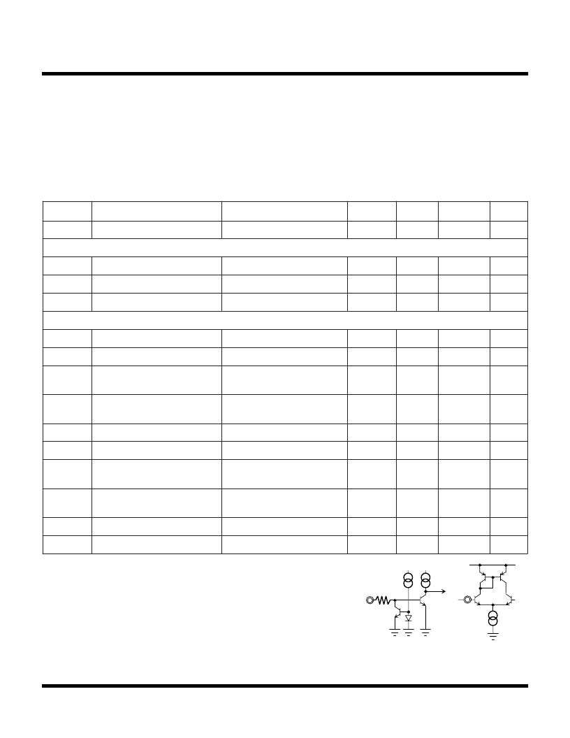
Note 1: The KEY input equivalent circuit is shown in Figure A.
When the control pin is open, it is outputted low level. The TK15328 is controlled by two
values,
and the function table is described in the block diagram.
Note 2: The specification means a value as measurement-input terminal connects to ground
through a capacitor.
Note 3: ISO is a cross talk between A channel and B channel, SEP is a cross talk between 1
channel and 2 channel. The specification means a value as measurement-input terminal
connects to ground through 10 k
resistor and capacitor.
Note 4: Input equivalent circuit is shown in Figure B. The standard application of TK15328M is
the direct connecting with the GND bias. When connecting a capacitor, then to supply a
bias voltage from GND to input be any resistor is necessary.
Note 5: Power dissipation is 350 mW when mounted as recommended. Derate at 3.0 mW/
°
C
for operation above 25
°
C.
Figure A
Figure B
相關(guān)PDF資料 |
PDF描述 |
|---|---|
| TK15328MTL | Audio Analog Switch |
| TK15329MTL | Audio Analog Switch |
| TK15329 | Audio Analog Switch |
| TK15329M | Audio Analog Switch |
| TK15400MTL | 75 OHM VIDEO LINE DRIVER |
相關(guān)代理商/技術(shù)參數(shù) |
參數(shù)描述 |
|---|---|
| TK15328MTL | 制造商:TOKO 制造商全稱:TOKO, Inc 功能描述:Audio Analog Switch |
| TK15328MTL/328 | 制造商:TOKO 制造商全稱:TOKO, Inc 功能描述:Audio Analog Switch |
| TK15329 | 制造商:TOKO 制造商全稱:TOKO, Inc 功能描述:Audio Analog Switch |
| TK15329M | 制造商:TOKO 制造商全稱:TOKO, Inc 功能描述:Audio Analog Switch |
| TK15329MTL | 制造商:TOKO 制造商全稱:TOKO, Inc 功能描述:Audio Analog Switch |
發(fā)布緊急采購,3分鐘左右您將得到回復(fù)。