- 您現(xiàn)在的位置:買賣IC網(wǎng) > PDF目錄361483 > TK15323M (TOKO Inc.) Audio Analog Switch PDF資料下載
參數(shù)資料
| 型號: | TK15323M |
| 廠商: | TOKO Inc. |
| 英文描述: | Audio Analog Switch |
| 中文描述: | 音頻模擬開關(guān) |
| 文件頁數(shù): | 2/12頁 |
| 文件大?。?/td> | 201K |
| 代理商: | TK15323M |

Page 2
June 1999 TOKO, Inc.
TK15323
L
O
B
M
Y
S
R
E
T
E
M
A
R
A
P
S
N
O
I
D
N
O
C
T
S
E
T
N
I
M
P
Y
T
X
A
M
S
T
N
U
I
C
C
t
e
C
y
p
u
S
5
5
A
m
N
O
I
C
E
S
L
O
R
T
N
O
C
Y
E
K
V
L
l
v
e
L
w
o
L
e
g
a
V
t
p
n
1
e
N
3
8
+
V
V
H
I
l
v
e
L
h
g
H
e
g
a
V
t
p
n
8
V
C
C
3
+
V
I
Y
E
K
O
t
e
C
t
p
O
D
N
G
o
T
0
3
A
μ
I
Y
E
K
I
t
e
C
w
o
V
m
o
F
C
C
0
3
A
μ
N
O
I
C
E
S
H
C
T
W
S
G
O
L
A
N
A
D
H
T
n
o
D
c
o
m
r
H
l
T
V
N
I
z
H
k
1
=
f
m
r
V
1
=
3
0
0
6
0
0
%
N
L
e
s
N
l
u
d
e
R
2
e
N
0
1
s
m
r
V
μ
O
S
I
n
o
s
V
N
e
N
I
,
H
k
0
1
=
F
,
m
r
V
1
3
=
5
7
B
d
P
E
S
n
o
p
e
S
V
N
e
N
I
,
H
k
0
1
=
f
m
r
V
1
3
=
0
8
B
d
N
Y
D
l
v
e
L
l
n
g
t
p
n
m
u
m
i
a
M
%
1
=
D
H
T
,
H
k
1
=
f
0
s
m
r
V
A
V
G
n
G
e
g
a
V
z
H
k
0
2
~
=
f
0
B
d
V
t
e
c
l
n
m
r
T
t
p
O
e
g
-
p
a
V
n
V
o
t
o
d
m
o
e
g
a
v
y
p
u
S
e
=
V
T
U
O
2
-
V
T
U
O
V
T
U
O
2
+
V
V
t
e
c
e
g
a
V
l
n
m
r
T
e
c
n
t
p
O
e
D
l
n
n
a
h
c
e
m
a
s
n
e
e
w
t
B
3
7
V
m
I
N
I
t
e
C
s
a
t
p
n
4
e
N
5
A
μ
Z
T
U
O
e
c
n
a
d
e
p
m
I
p
O
e
c
n
a
d
e
p
m
I
C
D
0
2
ABSOLUTE MAXIMUM RATINGS
Supply Voltage ......................................................... 15 V
Power Dissipation (Note 5) ................................ 350 mW
Storage Temperature Range ................... -55 to +150
°
C
Operating Temperature Range ...................-20 to +75
°
C
CONTROL SECTION
Input Voltage ................................... -0.3 V to V
CC
+ 0.3 V
TK15323M ELECTRICAL CHARACTERISTICS
Test conditions: V
CC
= 8.0 V, T
A
= 25
°
C,
unless otherwise specified.
ANALOG SWITCH SECTION
Signal Input Voltage ........................ -0.3 V to V
+ 0.3 V
Signal Output Current ............................................. 3 mA
Operating Voltage Range................................. 3 to 14 V
Maximum Input Frequency..................................100 kHz
Input
VCC
Logic
Input Key
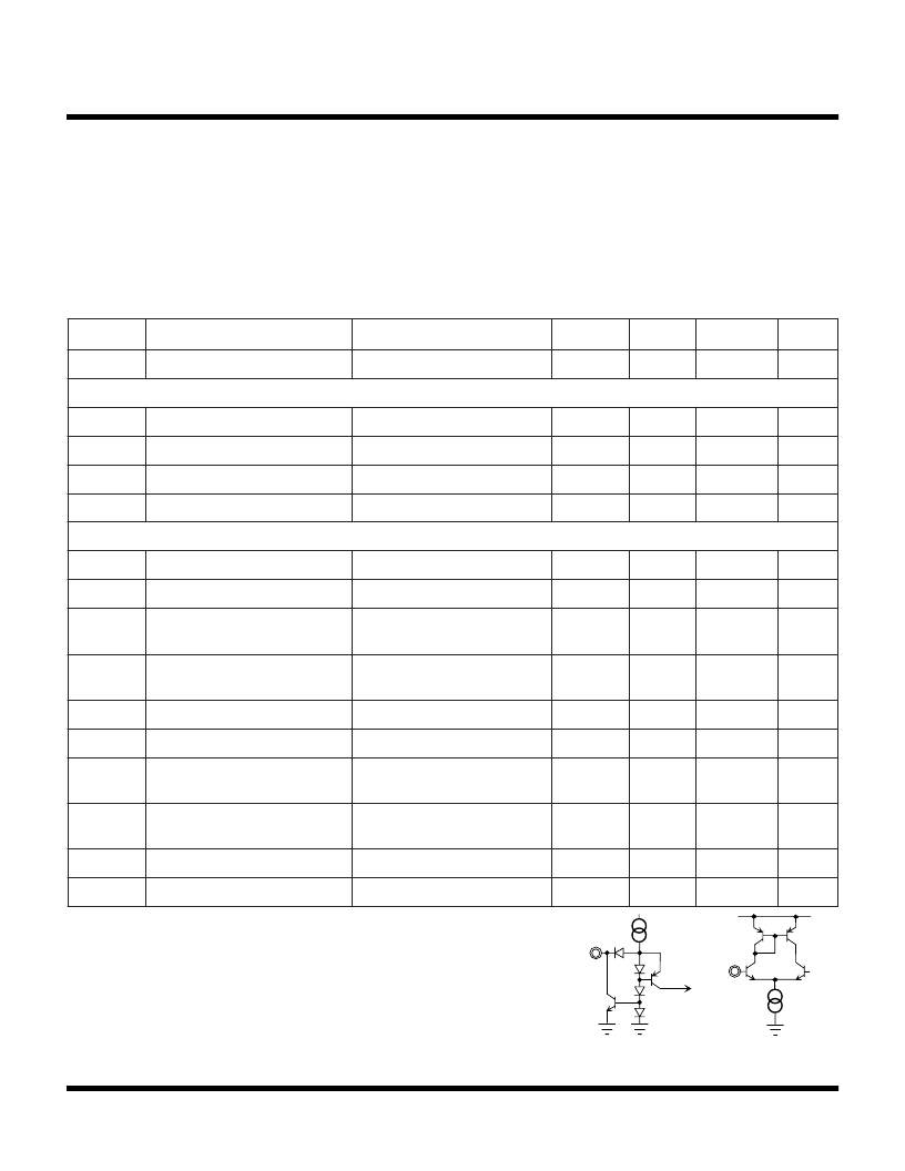
Note 1: The KEY input equivalent circuit is shown in Figure A.
1 channel and 2 channel is the separate action by 1Key pin and 2 key pin. When the control pin is
open, it is outputted high level (about 1.4 V). Then the A channel input signal is outputted. The
change is carried out at low level.
Note 2: The specification means a value as measurement-input terminal connects to ground
through a capacitor.
Note 3: ISO is a cross talk between A channel and B channel, SEP is a cross talk between 1 channel and 2
channel. The specification means a value as measurement-input termianl connects to ground
through 10 k
resistor and capacitor.
Note 4: Input equivalent circuit is shown in Figure B. The standard application of TK15323M is the direct
connecting. When connecting a capacitor, supplying a bias voltage from outside is unnecessary.
Note 5: Power dissipation is 350 mW when mounted as recommended. Derate at 3.0 mW/
°
C for operation
above 25
°
C.
Figure A
Figure B
相關(guān)PDF資料 |
PDF描述 |
|---|---|
| TK15323MTL | Audio Analog Switch |
| TK15324 | Audio Analog Switch |
| TK15324M | Audio Analog Switch |
| TK15324MTL | CABLE ASSEMBLY; LEAD-FREE SOLDER; SSMA MALE TO SSMA MALE; 50 OHM, RG178B/U COAX |
| TK15325MTL | Audio Analog Switch |
相關(guān)代理商/技術(shù)參數(shù) |
參數(shù)描述 |
|---|---|
| TK15323MTL | 制造商:TOKO 制造商全稱:TOKO, Inc 功能描述:Audio Analog Switch |
| TK15323MTL/323 | 制造商:TOKO 制造商全稱:TOKO, Inc 功能描述:Audio Analog Switch |
| TK15324 | 制造商:TOKO 制造商全稱:TOKO, Inc 功能描述:Audio Analog Switch |
| TK15324M | 制造商:TOKO 制造商全稱:TOKO, Inc 功能描述:Audio Analog Switch |
| TK15324MTL | 制造商:TOKO 制造商全稱:TOKO, Inc 功能描述:Audio Analog Switch |
發(fā)布緊急采購,3分鐘左右您將得到回復(fù)。