- 您現(xiàn)在的位置:買賣IC網(wǎng) > PDF目錄361483 > TK15210M (TOKO Inc.) Audio Analog Switch PDF資料下載
參數(shù)資料
| 型號: | TK15210M |
| 廠商: | TOKO Inc. |
| 英文描述: | Audio Analog Switch |
| 中文描述: | 音頻模擬開關(guān) |
| 文件頁數(shù): | 4/12頁 |
| 文件大小: | 94K |
| 代理商: | TK15210M |
Page 4
January 2000 TOKO, Inc.
TK15210
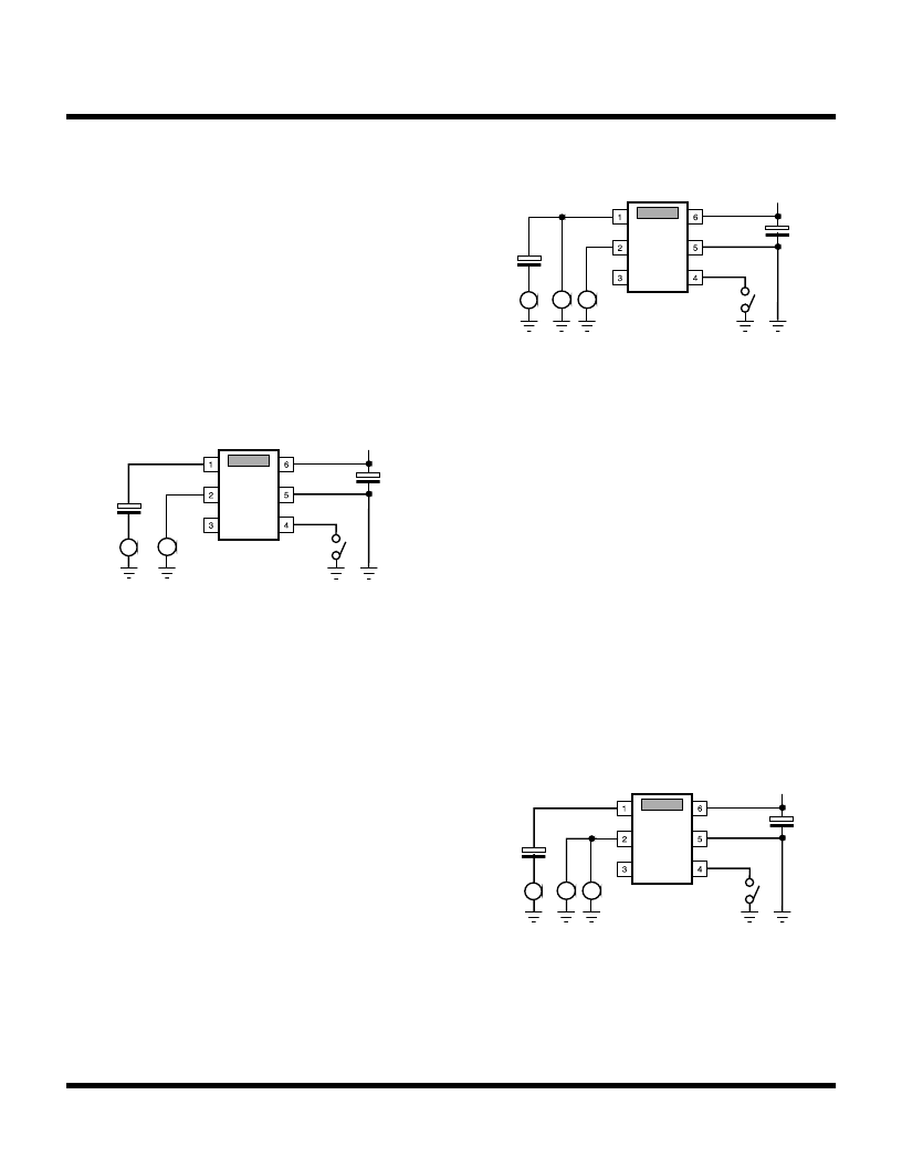
TOTAL HARMONIC DISTORTION (FIGURE 4)
Use the lower distortion oscillator for this measurement
because the distortion of the TK15210 is very low.
1) Pin 4 is in the open condition, or high level.
2) Connect a distortion analyzer to Pin 2.
3) Input a sine wave (1 kHz, 1 Vrms) to Pin 1.
4) Measure the distortion of Pin 2. This value is the
distortion of Ach.
5) Next connect Pin 4 to GND, or low level.
6) Input the same sine wave to Pin 3.
7) Measure in the same way. This value is the distortion
of Bch.
VOLTAGE GAIN (FIGURE 5)
This is the output level vs. the input level.
1) Pin 4 is in the open condition, or high level.
2) Connect AC volt meters to Pin 1 and Pin 3.
(For best results, use identical meters.)
3) Input a sine wave (1 kHz) to Pin 1 (f = optional up to max.
20 kHz, 1 Vrms).
4) Measure the level of Pin 1 and name this V1.
5) Measure the level of Pin 2 and name this V2.
6) Calculate Gain = 20 Log
(( |V2 - V1| )/V1)
V1<V2 = + Gain, V1>V2 = - Gain
This value is the voltage gain of Ach.
7) Next, connect Pin 4 to GND, or low level.
8) Input the same sine wave to Pin 3.
9) Measure and calculate in the same way.
This value is the voltage gain of Bch.
TEST CIRCUITS AND METHODS (CONT.)
VCC
+
+
~
THD
Figure 4
VCC
+
+
~
V
V
V1
V2
Figure 5
MAXIMUM INPUT LEVEL (FIGURE 6)
This measurement is made at the output side.
1) Pin 4 is in the open condition, or high level.
2) Connect a distortion analyzer and an AC volt meter to
Pin 2.
3) Input a sine wave (1 kHz) to Pin 1 and elevate the voltage
from 0 V gradually until the distortion gets to 0.1% at Pin
2.
4) When the distortion amounts to 0.1%, stop elevating and
measure the AC level of Pin 2.
This value is the maximum input level of Ach.
5) Next, connect Pin 4 to GND, or low level.
6) Input the same sine wave to Pin 3.
7) Measure in the same way.
This value is the maximum input level of Bch.
VCC
+
+
~
V
THD
Figure 6
相關(guān)PDF資料 |
PDF描述 |
|---|---|
| TK15210MTL | Audio Analog Switch |
| TK15211 | Audio Analog Switch |
| TK15211M | Audio Analog Switch |
| TK15211MTL | Audio Analog Switch |
| TK15220 | Audio Analog Switch |
相關(guān)代理商/技術(shù)參數(shù) |
參數(shù)描述 |
|---|---|
| TK15210MTL | 制造商:TOKO 制造商全稱:TOKO, Inc 功能描述:Audio Analog Switch |
| TK15210MTL/S1 | 制造商:TOKO 制造商全稱:TOKO, Inc 功能描述:Audio Analog Switch |
| TK15211 | 制造商:TOKO 制造商全稱:TOKO, Inc 功能描述:Audio Analog Switch |
| TK15211M | 制造商:TOKO 制造商全稱:TOKO, Inc 功能描述:Audio Analog Switch |
| TK15211MTL | 制造商:TOKO 制造商全稱:TOKO, Inc 功能描述:Audio Analog Switch |
發(fā)布緊急采購,3分鐘左右您將得到回復(fù)。