- 您現在的位置:買賣IC網 > PDF目錄361483 > TK15125MTL (TOKO INC) Dual Supply Grand Earthing System Audio Signal Mute IC PDF資料下載
參數資料
| 型號: | TK15125MTL |
| 廠商: | TOKO INC |
| 元件分類: | 消費家電 |
| 英文描述: | Dual Supply Grand Earthing System Audio Signal Mute IC |
| 中文描述: | SPECIALTY CONSUMER CIRCUIT, PDSO14 |
| 封裝: | SOP-14 |
| 文件頁數: | 2/8頁 |
| 文件大?。?/td> | 118K |
| 代理商: | TK15125MTL |
Page 2
July 1999 TOKO, Inc.
TK15125
L
O
B
M
Y
S
R
E
T
E
M
A
R
A
P
S
N
O
I
D
N
O
C
T
S
E
T
N
I
M
P
Y
T
X
A
M
S
T
N
U
V
D
D
e
g
a
V
g
n
p
O
5
0
5
V
V
S
S
5
0
5
V
I
)
F
F
O
(
D
D
f
O
e
M
,
e
C
g
n
p
O
6
9
A
m
I
)
N
O
(
D
D
n
O
e
M
,
e
C
g
n
p
O
0
1
0
1
A
m
T
T
A
n
o
u
n
e
A
R
N
I
0
0
3
=
)
e
N
(
5
8
9
8
B
d
I
C
N
O
t
e
C
e
g
h
C
n
O
e
M
0
0
1
0
1
A
μ
I
C
F
F
O
t
e
C
e
g
h
c
s
D
f
O
e
M
)
e
N
(
8
0
0
A
μ
V
W
S
F
F
O
f
O
e
M
,
W
S
l
o
e
C
g
e
M
a
V
V
S
S
V
S
S
4
+
V
V
W
S
N
O
n
O
e
M
,
W
S
l
o
e
C
g
e
M
a
V
V
S
S
4
+
V
D
D
V
I
W
S
N
O
n
O
e
M
,
W
S
l
o
t
C
e
M
e
C
6
1
5
2
A
μ
V
T
A
S
O
e
g
a
V
C
D
t
p
O
n
O
e
M
4
7
V
m
1
D
H
T
c
o
m
r
H
l
T
n
f
O
e
M
o
D
5
2
0
0
0
7
0
0
%
2
D
H
T
N
O
r
A
-
S
I
7
0
0
0
0
3
0
0
%
A
V
G
n
G
e
g
a
V
z
H
k
0
2
~
=
B
d
5
0
5
+
B
d
V
)
X
A
M
(
N
I
e
g
a
V
t
p
n
m
u
m
i
a
M
%
1
0
<
D
H
T
2
V
P
-
P
R
M
e
c
n
a
e
R
n
o
u
n
e
A
r
n
n
8
6
1
0
4
2
2
1
3
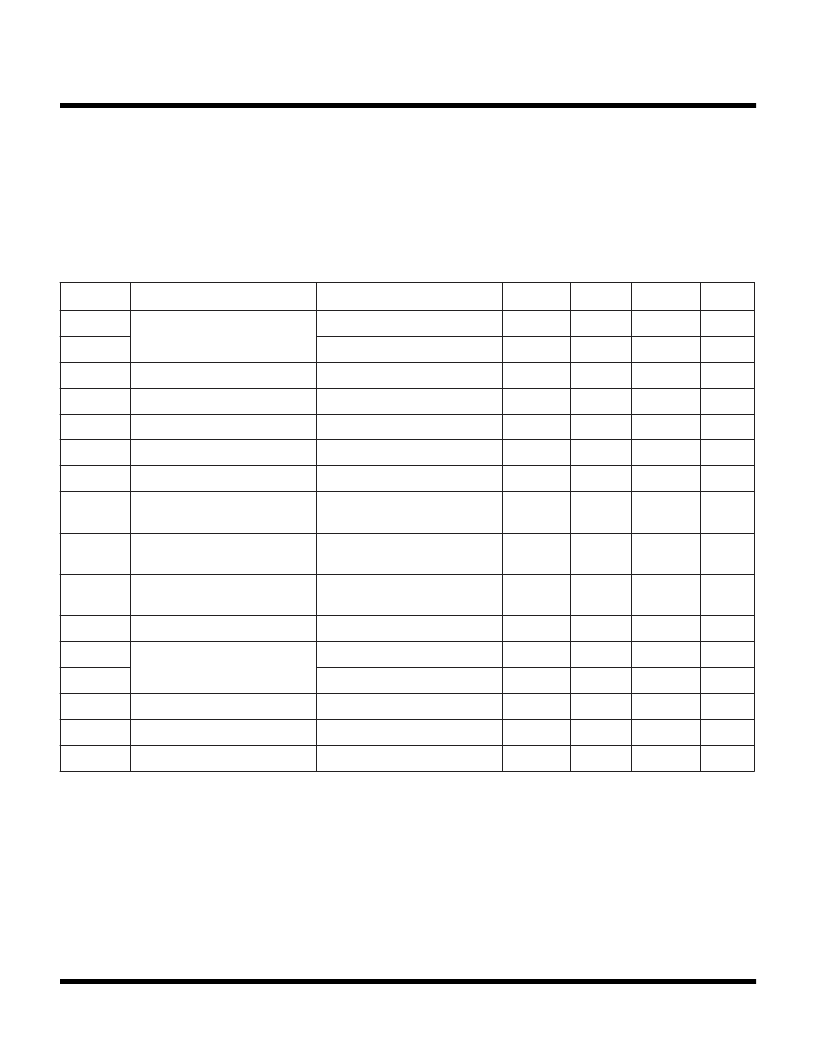
ABSOLUTE MAXIMUM RATINGS
Storage Temperature Range ................... -55 to +150
°
C
Operating Temperature Range ...................-20 to +60
°
C
Signal Input Voltage ......................................... V
SS
to V
DD
TK15121M ELECTRICAL CHARACTERISTICS
Test conditions: V
CC
=
±
5 V, T
A
= 25
°
C, f = 1 kHz, V
SIN
= 5 V
P-P
unless otherwise specified.
Note 1: If an R
other than 300
is used, the volume attenuation and attack/release times change.
Note 2: In the standard application a capacitor is connected between Pin 13 and V
. Attack is the term used to describe the action of changing the
unit from ‘mute off’ to ’mute on’. Release is the term used to describe the action of changing the unit from ‘mute on’ to ‘mute off’. The standard
timing control capacitance is 0.047
μ
F.
Note 3: Power dissipation is 350 mW when mounted as recommended. Derate at 2.8 mW/
°
C for operation above 25
°
C.
Supply Voltage .........................................................
±
6 V
Power Dissipation (Note 3) ................................ 350 mW
Input Frequency ..................................................100 kHz
相關PDF資料 |
PDF描述 |
|---|---|
| TK15210 | Audio Analog Switch |
| TK15210M | Audio Analog Switch |
| TK15210MTL | Audio Analog Switch |
| TK15211 | Audio Analog Switch |
| TK15211M | Audio Analog Switch |
相關代理商/技術參數 |
參數描述 |
|---|---|
| TK15125MTL/15125 | 制造商:TOKO 制造商全稱:TOKO, Inc 功能描述:Dual Supply Grand Earthing System Audio Signal Mute IC |
| TK15210 | 制造商:TOKO 制造商全稱:TOKO, Inc 功能描述:Audio Analog Switch |
| TK15210M | 制造商:TOKO 制造商全稱:TOKO, Inc 功能描述:Audio Analog Switch |
| TK15210MTL | 制造商:TOKO 制造商全稱:TOKO, Inc 功能描述:Audio Analog Switch |
| TK15210MTL/S1 | 制造商:TOKO 制造商全稱:TOKO, Inc 功能描述:Audio Analog Switch |
發(fā)布緊急采購,3分鐘左右您將得到回復。