- 您現(xiàn)在的位置:買賣IC網(wǎng) > PDF目錄361482 > TK11830M (TOKO INC) POSITIVE-TO-NEGATIVE DC-DC CONVERTER PDF資料下載
參數(shù)資料
| 型號: | TK11830M |
| 廠商: | TOKO INC |
| 元件分類: | 基準電壓源/電流源 |
| 英文描述: | POSITIVE-TO-NEGATIVE DC-DC CONVERTER |
| 中文描述: | 1-OUTPUT DC-DC REG PWR SUPPLY MODULE |
| 封裝: | SOT-23L, 6 PIN |
| 文件頁數(shù): | 10/13頁 |
| 文件大小: | 85K |
| 代理商: | TK11830M |
Page 10
January 1999 TOKO, Inc.
TK11830
APPLICATION INFORMATION
COMPONENT REQUIREMENTS
Inductor
DC resistance of the inductor must be less than 5
. For
optimal performance and efficiency, an inductor with a DC
resistance of less than 1
is recommended. The oscillator
frequency is inversely proportional to inductance. The
inductance should be greater than 300
μ
H to prevent loss
of efficiency at high frequencies.
There is a large peak current (up to I
LPK
= 300mA) when
the inductor is saturated.
C
FB
, C
REF
, C
IN
, C
OUT
The filtered output ripple is fed back to the feedback pin. To
ensure continuous operation, C
FB
should be connected
between the feedback pin and ground. If a large voltage is
fed back to the feedback pin, the power transistor switch
drive will be intermittent. This causes a large ripple voltage
since I
LPK
becomes larger. The value of C
FB
is determined
by the value of the output capacitor, C
OUT,
and the feedback
resistance, R
2
. The feedback capacitor must be larger
when the ripple voltage is high due to the lower C
OUT
. C
REF
is used to prevent oscillation of the band gap reference and
to stabilize the feedback loop. The input capacitor, C
IN
, is
used to reduce supply impedance and to provide sufficient
input current during switching for stable circuit operation.
Recommended values:
C
REF
> 0.1
μ
F
C
FB
> 0.01
μ
F
C
IN
> 22
μ
F
C
OUT
> 22
μ
F
Note: C
OUT
should be sufficiently large and have a low
ESR to minimize ripple voltage.
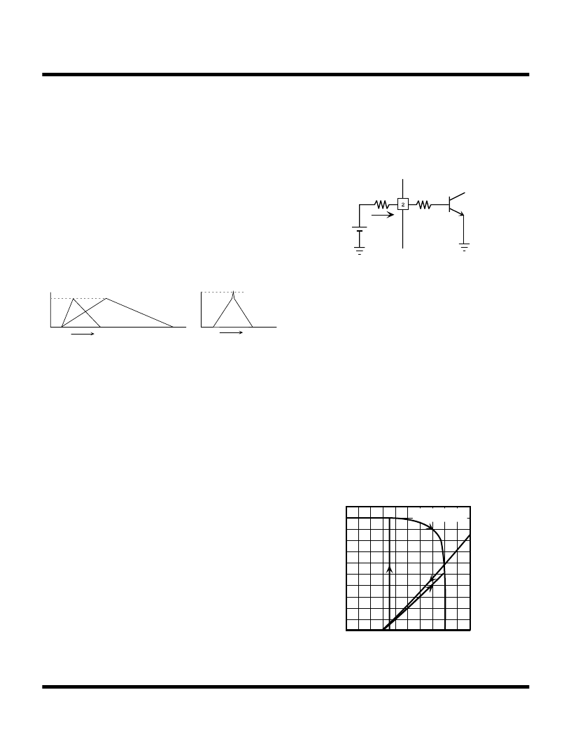
Control Pin Resistor (R
CONT
)
Input requirements of the Control pin are as follows:
When V
CONT
is high (above 2.2 V), the circuit operation is
stopped. When V
CONT
is low (below 0.4 V), operation is
resumed.
A control current of 3
μ
A (typ.) is required for shutdown.
Shutdown voltage, V
CONT
, is related to the resistance
R
CONT
as shown below. V
CONT
changes when R
CONT
is
changed.
V
CONT
~ R
CONT
x I
CONT
+ V
BE
V
CONT
~ (300 k
) x (3
μ
A) + 0.7 V = 1.60 V at
R
SD
= 300 k
and V
BE
~ 0.7 V
ICONT
+
VCONT
RCONT
VBE
30 k
ON/OFF CONTROL
-4
-2
V
-5
-3
-1
VCONT
0
TA = 25
°
C
0 1 2
I
4
2
5
3
1
0
ILPK
IL
t
L(SMALL)
L(LARGE)
t
ILPK(MAX)
-300 mA
INDUCTOR
相關(guān)PDF資料 |
PDF描述 |
|---|---|
| TK11830MTL | POSITIVE-TO-NEGATIVE DC-DC CONVERTER |
| TK11830 | POSITIVE-TO-NEGATIVE DC-DC CONVERTER |
| TK11835MTL | POSITIVE TO NEGATIVE DC-DC CONVERTER |
| TK11835 | POSITIVE TO NEGATIVE DC-DC CONVERTER |
| TK11855F-G | Step-up DC-DC converter IC |
相關(guān)代理商/技術(shù)參數(shù) |
參數(shù)描述 |
|---|---|
| TK118A | 制造商:Thomas & Betts 功能描述:Fittings Coupler 3inch Steel |
| TK118A-RT | 制造商:Thomas & Betts 功能描述:3 IN RAINTIGHT COMPRESSION CPL |
| TK11950MTL | 制造商:TOKO 功能描述: |
| TK119A | 制造商:Thomas & Betts 功能描述:3 1/2" COUPLING,COMP.,EMT,STL 制造商:Thomas & Betts 功能描述:Fittings Coupler 3.5inch Steel |
| TK119A-RT | 制造商:Thomas & Betts 功能描述:3 1/2 IN RAINTIGHT COMPRESSION CPL |
發(fā)布緊急采購,3分鐘左右您將得到回復。