- 您現(xiàn)在的位置:買賣IC網(wǎng) > PDF目錄384000 > TISP7380F3D-S (BOURNS INC) MEDIUM & HIGH-VOLTAGE TRIPLE ELEMENT BIDIRECTIONAL THYRISTOR OVERVOLTAGE PROTECTORS PDF資料下載
參數(shù)資料
| 型號: | TISP7380F3D-S |
| 廠商: | BOURNS INC |
| 元件分類: | 浪涌電流限制器 |
| 英文描述: | MEDIUM & HIGH-VOLTAGE TRIPLE ELEMENT BIDIRECTIONAL THYRISTOR OVERVOLTAGE PROTECTORS |
| 中文描述: | 380 V, 4.3 A, SILICON SURGE PROTECTOR, MS-012AA |
| 封裝: | ROHS COMPLIANT, SOP-8 |
| 文件頁數(shù): | 6/19頁 |
| 文件大小: | 562K |
| 代理商: | TISP7380F3D-S |
MARCH 1994 - REVISED MARCH 2006
Specifications are subject to change without notice.
Customers should verify actual device performance in their specific applications.
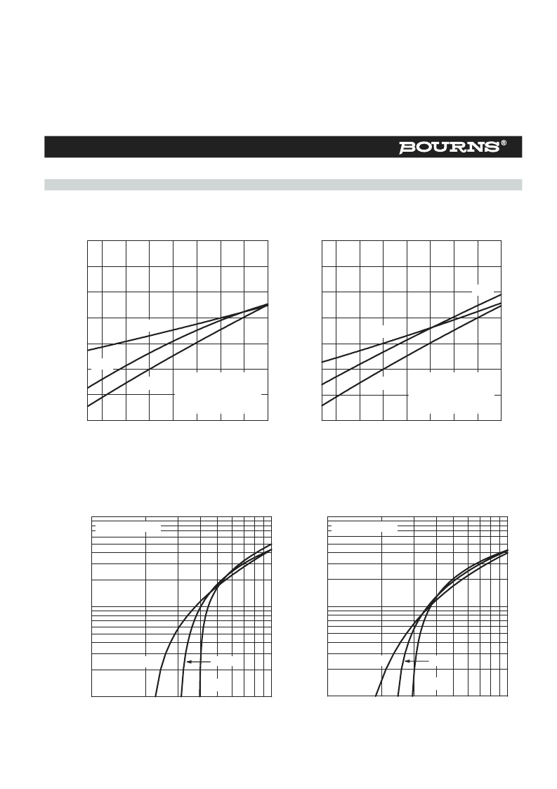
Typical Characteristics - R and G, or T and G Terminals
TISP7xxxF3 (MV, HV) Overvoltage Protector Series
Figure 6.
Figure 7.
Figure 8.
Figure 9.
T
J
- Junction Temperature -
°
C
-25
0
25
50
75
100
125
150
0.9
1.0
1.1
1.2
TC7MAF
V
(BO)
V
(BR)
V
(BR)M
Negative Polarity
Normalized to V
(BR)
I
(BR)
= 1 mA and 25
°
C
Junction Temperature -
°
C
T
J
-
-25
0
25
50
75
100
125
150
0.9
1.0
1.1
1.2
TC7HAF
V
(BO)
V
(BR)
V
(BR)M
Negative Polarity
Normalized to V
(BR)
I
(BR)
= 1 mA and 25
°
C
V
T
- On-State Voltage - V
2
3
4
5
6
7 8 9
1
10
10
I
T
1
10
100
TC7MAL
Positive Polarity
V
T
- On-State Voltage - V
2
3
4
5
6
7 8 9
1
I
T
1
10
100
TC7HAL
150
°
C
Positive Polarity
TISP7125F3 THRU TISP7180F3
NORMALIZED BREAKDOWN VOLTAGES
vs
JUNCTION TEMPERATURE
TISP7240F3 THRU TISP7380F3
NORMALIZED BREAKDOWN VOLTAGES
vs
JUNCTION TEMPERATURE
ON-STATE CURRENT
vs
ON-STATE VOLTAGE
ON-STATE CURRENT
vs
ON-STATE VOLTAGE
25
°
C
25
°
C
-40
°
C
-40
°
C
150
°
C
N
N
相關(guān)PDF資料 |
PDF描述 |
|---|---|
| TISP7380F3SL | MEDIUM & HIGH-VOLTAGE TRIPLE ELEMENT BIDIRECTIONAL THYRISTOR OVERVOLTAGE PROTECTORS |
| TISP7380F3SL-S | MEDIUM & HIGH-VOLTAGE TRIPLE ELEMENT BIDIRECTIONAL THYRISTOR OVERVOLTAGE PROTECTORS |
| TISP7150F3SL-S | MEDIUM & HIGH-VOLTAGE TRIPLE ELEMENT BIDIRECTIONAL THYRISTOR OVERVOLTAGE PROTECTORS |
| TISP7180F3D | MEDIUM & HIGH-VOLTAGE TRIPLE ELEMENT BIDIRECTIONAL THYRISTOR OVERVOLTAGE PROTECTORS |
| TISP7180F3DR | MEDIUM & HIGH-VOLTAGE TRIPLE ELEMENT BIDIRECTIONAL THYRISTOR OVERVOLTAGE PROTECTORS |
相關(guān)代理商/技術(shù)參數(shù) |
參數(shù)描述 |
|---|---|
| TISP7380F3P | 功能描述:硅對稱二端開關(guān)元件 Triple Element Bidirectional RoHS:否 制造商:Bourns 轉(zhuǎn)折電流 VBO:40 V 最大轉(zhuǎn)折電流 IBO:800 mA 不重復(fù)通態(tài)電流: 額定重復(fù)關(guān)閉狀態(tài)電壓 VDRM:25 V 關(guān)閉狀態(tài)漏泄電流(在 VDRM IDRM 下): 保持電流(Ih 最大值):50 mA 開啟狀態(tài)電壓:5 V 關(guān)閉狀態(tài)電容 CO:120 pF 最大工作溫度:+ 150 C 安裝風(fēng)格:SMD/SMT 封裝 / 箱體:DO-214AA |
| TISP7380F3PS | 制造商:Bourns Inc 功能描述: |
| TISP7380F3P-S | 功能描述:硅對稱二端開關(guān)元件 Triple Element Bidirectional RoHS:否 制造商:Bourns 轉(zhuǎn)折電流 VBO:40 V 最大轉(zhuǎn)折電流 IBO:800 mA 不重復(fù)通態(tài)電流: 額定重復(fù)關(guān)閉狀態(tài)電壓 VDRM:25 V 關(guān)閉狀態(tài)漏泄電流(在 VDRM IDRM 下): 保持電流(Ih 最大值):50 mA 開啟狀態(tài)電壓:5 V 關(guān)閉狀態(tài)電容 CO:120 pF 最大工作溫度:+ 150 C 安裝風(fēng)格:SMD/SMT 封裝 / 箱體:DO-214AA |
| TISP7380F3SL | 功能描述:硅對稱二端開關(guān)元件 Triple Element Bidirectional RoHS:否 制造商:Bourns 轉(zhuǎn)折電流 VBO:40 V 最大轉(zhuǎn)折電流 IBO:800 mA 不重復(fù)通態(tài)電流: 額定重復(fù)關(guān)閉狀態(tài)電壓 VDRM:25 V 關(guān)閉狀態(tài)漏泄電流(在 VDRM IDRM 下): 保持電流(Ih 最大值):50 mA 開啟狀態(tài)電壓:5 V 關(guān)閉狀態(tài)電容 CO:120 pF 最大工作溫度:+ 150 C 安裝風(fēng)格:SMD/SMT 封裝 / 箱體:DO-214AA |
| TISP7380F3SLS | 制造商:Bourns Inc 功能描述: |
發(fā)布緊急采購,3分鐘左右您將得到回復(fù)。