- 您現(xiàn)在的位置:買賣IC網(wǎng) > PDF目錄98229 > THS8133BCPHP (TEXAS INSTRUMENTS INC) PARALLEL, WORD INPUT LOADING, 0.005 us SETTLING TIME, 10-BIT DAC, PQFP48 PDF資料下載
參數(shù)資料
| 型號: | THS8133BCPHP |
| 廠商: | TEXAS INSTRUMENTS INC |
| 元件分類: | DAC |
| 英文描述: | PARALLEL, WORD INPUT LOADING, 0.005 us SETTLING TIME, 10-BIT DAC, PQFP48 |
| 封裝: | GREEN, PLASTIC, HTQFP-48 |
| 文件頁數(shù): | 2/25頁 |
| 文件大?。?/td> | 549K |
| 代理商: | THS8133BCPHP |

THS8133, THS8133A, THS8133B
TRIPLE 10BIT, 80 MSPS VIDEO D/A CONVERTER
WITH TRILEVEL SYNC GENERATION
SLVS204C APRIL 1999 REVISED SEPTEMBER 2000
10
POST OFFICE BOX 655303
DALLAS, TEXAS 75265
POST OFFICE BOX 1443
HOUSTON, TEXAS 772511443
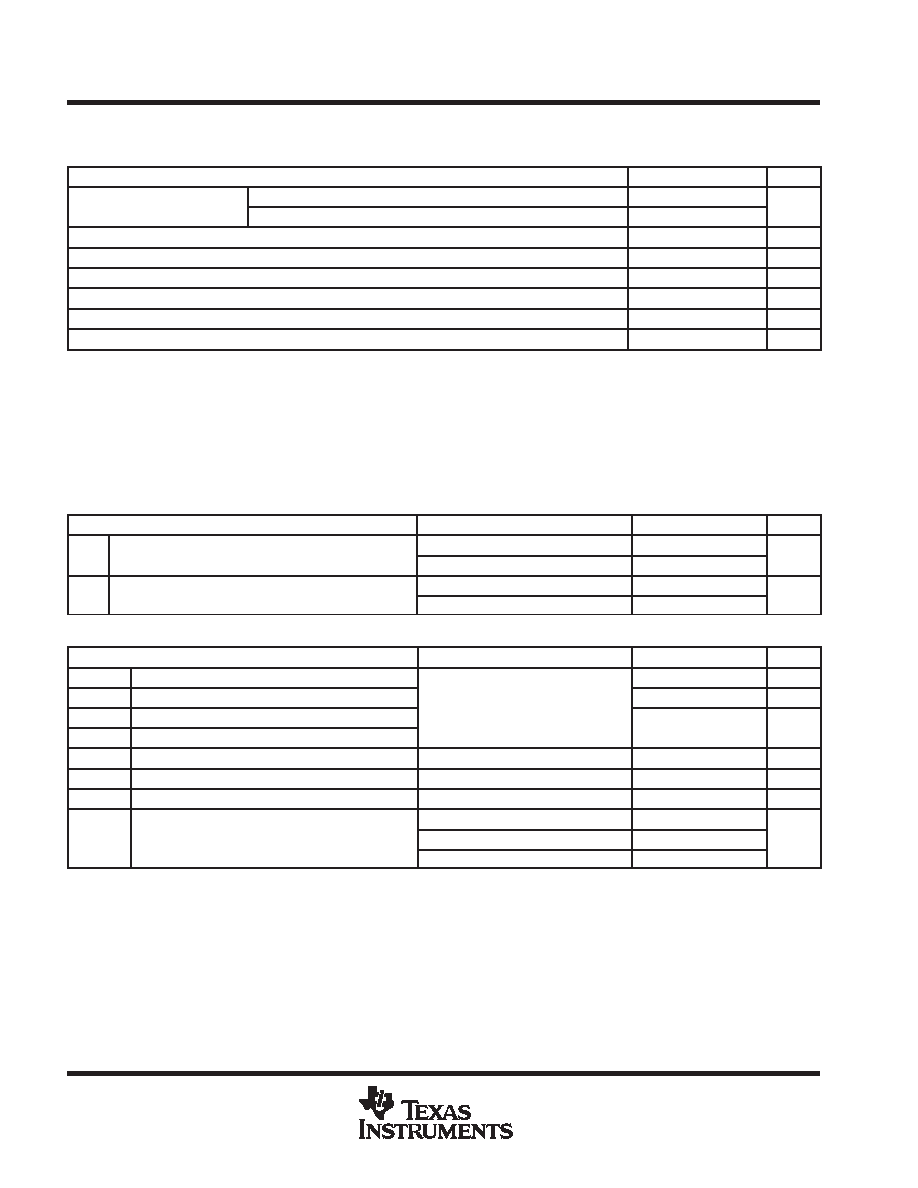
recommended operating conditions over operating free-air temperature range, TA (continued)
digital and reference inputs
MIN
NOM
MAX
UNIT
High-level input voltage, VIH
DVDD = 3.3 V
2
DVDD
V
High-level input voltage, VIH
DVDD = 5 V
2.4
DVDD
V
Lowlevel input voltage, VIL
DVSS
0.8
V
Clock frequency, fclk
0
80
MHz
Pulse duration, clock high, tw(CLKH)
5
ns
Pulse duration, clock low, tw(CLKL)
5
ns
Reference input voltage, Vref(I) (see Note 3)
1.35
1.62
V
FSADJ resistor, R(FS) (see Note 3)
360
430
Voltage reference input applies to the externally applied voltage (overdrive condition). Internally a 2 k resistor isolates the internal reference
from the externally applied voltage, if any.
NOTE 3: The combination of Vref and RFS can be chosen at will as long as the maximum full-scale DAC output current I(FS) does not exceed 120%
of its nominal value. Therefore, at fixed R(FS) = R(FSnom), Vref should not be higher than the maximum value mentioned and at fixed
Vref = Vref(nom), R(FS) should not be less than the minimum value mentioned.
electrical characteristics over recommended operating conditions with fCLK = 80 MSPS and use
of internal reference voltage Vref, with R(FS) = R(FSnom) (unless otherwise noted)
power supply (1 MHz, 1 dBFS digital sine simultaneously applied to all 3 channels)
PARAMETER
TEST CONDITIONS
MIN
TYP
MAX
UNIT
IDD
Operating supply current
AVDD = DVDD = 5 V
134
142
mA
IDD
Operating supply current
AVDD = 5 V, DVDD = 3.3
114
121
mA
PD
Power dissipation
AVDD = DVDD = 5 V
670
710
mW
PD
Power dissipation
AVDD = 5 V, DVDD = 3.3
525
565
mW
digital inputs dc characteristics
PARAMETER
TEST CONDITIONS
MIN
TYP
MAX
UNIT
IIH
High-level input current
AV
= DV
= 5 V
1
A
IIL
Low-level input current
AVDD = DVDD = 5 V
Digital inputs and CLK at 0 V for IIL;
1
A
IIL(CLK)
Low-level input current, CLK
DD
Digital inputs and CLK at 0 V for IIL;
Digital inputs and CLK at 5 V for IIH
1
A
IIH(CLK)
High-level input current, CLK
Digital inputs and CLK at 5 V for IIH
1
A
CI
Input capacitance
TA = 25_C
7
pF
ts
Data and control inputs setup time
3
ns
tH
Data and control inputs hold time
0
ns
Digital process delay from first registered color
RGB and YPbPr 4:4:4
7
CLK
td(D)
Digital process delay from first registered color
component of pixel (see Figures 35)
YPbPr 4:2:2 2
×10 bit
8
CLK
periods
td(D)
component of pixel (see Figures 35)
YPbPr 4:2:2 1
×10 bit
9
periods
This parameter is assured by design and not production tested. The digital process delay is defined as the number of CLK cycles required for
the first registered color component of a pixel, starting from the time of registering it on the input bus, to propagate through all processing and
appear at the DAC output drivers. The remaining delay through the IC is the analog delay td(A) of the analog output drivers.
相關(guān)PDF資料 |
PDF描述 |
|---|---|
| THS8133BCPHPG4 | PARALLEL, WORD INPUT LOADING, 0.005 us SETTLING TIME, 10-BIT DAC, PQFP48 |
| THS8133CPHP | PARALLEL, WORD INPUT LOADING, 0.005 us SETTLING TIME, 10-BIT DAC, PQFP48 |
| THS8134BCPHP | PARALLEL, 8 BITS INPUT LOADING, 0.005 us SETTLING TIME, 8-BIT DAC, PQFP48 |
| THS8134CPHP | PARALLEL, 8 BITS INPUT LOADING, 0.005 us SETTLING TIME, 8-BIT DAC, PQFP48 |
| THS8134ACPHP | PARALLEL, 8 BITS INPUT LOADING, 0.005 us SETTLING TIME, 8-BIT DAC, PQFP48 |
相關(guān)代理商/技術(shù)參數(shù) |
參數(shù)描述 |
|---|---|
| THS8133BCPHPG4 | 制造商:TI 制造商全稱:Texas Instruments 功能描述:TRIPLE 10-BIT, 80 MSPS VIDEO D/A CONVERTER WITH TRI-LEVEL SYNC GENERATION WITH TRI-LEVEL SYNC GENERATION |
| THS8133BEVM | 制造商:Texas Instruments 功能描述:THS8133B TRIPLE 10BIT 80MSPS VID DAC EVM - Bulk |
| THS8133CPHP | 制造商:TI 制造商全稱:Texas Instruments 功能描述:TRIPLE 10-BIT, 80 MSPS VIDEO D/A CONVERTER WITH TRI-LEVEL SYNC GENERATION |
| THS8133TQFP | 制造商:TI 制造商全稱:Texas Instruments 功能描述:TRIPLE 10-BIT, 80 MSPS VIDEO D/A CONVERTER WITH TRI-LEVEL SYNC GENERATION |
| THS8134 | 制造商:TI 制造商全稱:Texas Instruments 功能描述:TRIPLE 8-BIT, 80 MSPS VIDEO D/A CONVERTER WITH TRI-LEVEL SYNC GENERATION |
發(fā)布緊急采購,3分鐘左右您將得到回復(fù)。