- 您現(xiàn)在的位置:買賣IC網(wǎng) > PDF目錄98229 > THS7374IPWRG4 (TEXAS INSTRUMENTS INC) 4 CHANNEL, VIDEO AMPLIFIER, PDSO14 PDF資料下載
參數(shù)資料
| 型號(hào): | THS7374IPWRG4 |
| 廠商: | TEXAS INSTRUMENTS INC |
| 元件分類: | 音頻/視頻放大 |
| 英文描述: | 4 CHANNEL, VIDEO AMPLIFIER, PDSO14 |
| 封裝: | GREEN, PLASTIC, TSSOP-14 |
| 文件頁(yè)數(shù): | 13/40頁(yè) |
| 文件大?。?/td> | 929K |
| 代理商: | THS7374IPWRG4 |
第1頁(yè)第2頁(yè)第3頁(yè)第4頁(yè)第5頁(yè)第6頁(yè)第7頁(yè)第8頁(yè)第9頁(yè)第10頁(yè)第11頁(yè)第12頁(yè)當(dāng)前第13頁(yè)第14頁(yè)第15頁(yè)第16頁(yè)第17頁(yè)第18頁(yè)第19頁(yè)第20頁(yè)第21頁(yè)第22頁(yè)第23頁(yè)第24頁(yè)第25頁(yè)第26頁(yè)第27頁(yè)第28頁(yè)第29頁(yè)第30頁(yè)第31頁(yè)第32頁(yè)第33頁(yè)第34頁(yè)第35頁(yè)第36頁(yè)第37頁(yè)第38頁(yè)第39頁(yè)第40頁(yè)

75 W
Y'/G'Out
CVBS/Sync
CVBS
+3.3V
R
DAC/Encoder
SDTV
CVBS
S-Video
Y'P' P'
R'G'B'
B
R
Y'/G'
R
P’ /B'
B
R
P’ /R'
R
1
2
3
4
5
6
7
14
13
12
11
10
9
8
CH1OUT
CH2OUT
CH3OUT
CH4OUT
V
S+
BYPASS
NC
CH1IN
CH2IN
CH3IN
CH4IN
GND
DISABLE
NC
THS7374
ToGPIOController
orGND
75 W
P' /B'Out
B
75 W
P' /R'Out
R
75 W
+3Vto+5V
SLOS590B – JULY 2008 – REVISED JANUARY 2011
www.ti.com
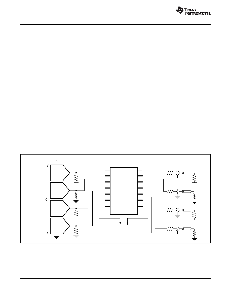
TYPICAL CONFIGURATION AND VIDEO
This rationale is also used for the chroma (C') term.
TERMINOLOGY
Chroma is derived from the non-linear R'G'B' terms
and thus it is nonlinear. Chominance (C) is derived
A typical application circuit that uses the THS7374 as
from linear RGB, giving the difference between
a video buffer is shown in Figure 57. It shows a DAC
chroma
(C')
and
chrominance
(C).
The
color
or
encoder
driving
the
input
channels
of
the
difference signals (P'B/P'R/U'/V') are also referenced
THS7374. One channel is a composite video (CVBS)
in
this
way
to
denote
the
nonlinear
(gamma
channel of a standard definition (SD) video system.
corrected) signals.
The other channels are the component video Y'P'BP'R
(sometimes labeled Y'U'V' or incorrectly labeled
R'G'B' (commonly mislabeled RGB) is also called
Y'C'BC'R) signals of a 480i or 576i system. These
G'B'R' (again commonly mislabeled as GBR) in
channels could easily be the s-video Y'/C' channels
professional video systems. The SMPTE component
or the R'G'B' channels of a SCART system.
standard stipulates that the luma information is
placed on the first channel, the blue color difference
Note that the Y' term is used for the luma channels
is placed on the second channel, and the red color
throughout this document rather than the more
difference signal is placed on the third channel. This
common luminance (Y) term. The reason for this
configuration
is
consistent
with
the
Y'P'BP'R
usage is to account for the definition of luminance as
nomenclature. Because the luma channel (Y') carries
stipulated by the CIE (International Commission on
the sync information and the green channel (G') also
Illumination). Video departs from true luminance
carries the sync information, it makes logical sense
because a nonlinear term, gamma, is added to the
that G' be placed first in the system. Furthermore,
true RGB signals to form R'G'B' signals. These R'G'B'
because the blue color difference channel (P'B) is
signals are then used to mathematically create luma
next and the red color difference channel (P'R) is last,
(Y'). Thus, luminance (Y) is not maintained, providing
then it also makes logical sense to place the B' signal
a difference in terminology.
on the second channel and the R' signal on the third
channel respectfully. Thus, hardware compatibility is
better achieved when using G'B'R' rather than R'G'B'.
Note that for many G'B'R' systems, sync is embedded
on all three channels, but this may not always be the
case in all systems.
Figure 57. Typical SDTV CVBS/Y'P'BP'R Inputs from DC-Coupled Encoder/DAC
with DC-Coupled Line Driving
20
Copyright 2008–2011, Texas Instruments Incorporated
Product Folder Link(s): THS7374
相關(guān)PDF資料 |
PDF描述 |
|---|---|
| THS7375IPWR | VIDEO AMPLIFIER, PDSO14 |
| THS7375IPW | VIDEO AMPLIFIER, PDSO14 |
| THS7375IPWG4 | VIDEO AMPLIFIER, PDSO14 |
| THS7375IPWRG4 | VIDEO AMPLIFIER, PDSO14 |
| THS770012IRGET | SPECIALTY ANALOG CIRCUIT, PQCC24 |
相關(guān)代理商/技術(shù)參數(shù) |
參數(shù)描述 |
|---|---|
| THS7375 | 制造商:TI 制造商全稱:Texas Instruments 功能描述:4-Channel SDTV Video Amplifier with 6th-Order Filters and 5.6-V/V Gain |
| THS7375EVM | 功能描述:放大器 IC 開發(fā)工具 THS7375 Eval Mod RoHS:否 制造商:International Rectifier 產(chǎn)品:Demonstration Boards 類型:Power Amplifiers 工具用于評(píng)估:IR4302 工作電源電壓:13 V to 23 V |
| THS7375IPW | 功能描述:視頻放大器 4Ch SDTV Video Amp RoHS:否 制造商:ON Semiconductor 通道數(shù)量:4 電源類型: 工作電源電壓:3.3 V, 5 V 電源電流: 最小工作溫度: 最大工作溫度: 封裝 / 箱體:TSSOP-14 封裝:Reel |
| THS7375IPWG4 | 功能描述:視頻放大器 4Ch SDTV Video Amp w/6th order fltr RoHS:否 制造商:ON Semiconductor 通道數(shù)量:4 電源類型: 工作電源電壓:3.3 V, 5 V 電源電流: 最小工作溫度: 最大工作溫度: 封裝 / 箱體:TSSOP-14 封裝:Reel |
| THS7375IPWR | 功能描述:視頻放大器 4Ch SDTV Video Amp RoHS:否 制造商:ON Semiconductor 通道數(shù)量:4 電源類型: 工作電源電壓:3.3 V, 5 V 電源電流: 最小工作溫度: 最大工作溫度: 封裝 / 箱體:TSSOP-14 封裝:Reel |
發(fā)布緊急采購(gòu),3分鐘左右您將得到回復(fù)。