- 您現(xiàn)在的位置:買賣IC網(wǎng) > PDF目錄98220 > THS14F01IPFBG4 (TEXAS INSTRUMENTS INC) 1-CH 14-BIT PROPRIETARY METHOD ADC, PARALLEL ACCESS, PQFP48 PDF資料下載
參數(shù)資料
| 型號: | THS14F01IPFBG4 |
| 廠商: | TEXAS INSTRUMENTS INC |
| 元件分類: | ADC |
| 英文描述: | 1-CH 14-BIT PROPRIETARY METHOD ADC, PARALLEL ACCESS, PQFP48 |
| 封裝: | GREEN, PLASTIC, TQFP-48 |
| 文件頁數(shù): | 8/24頁 |
| 文件大小: | 329K |
| 代理商: | THS14F01IPFBG4 |
THS14F01, THS14F03
14-BIT, 1 MSPS/ 3 MSPS, DSP COMPATIBLE, ANALOG-TO-DIGITAL CONVERTERS
WITH FIFO INTERNAL REFERENCE AND PGA
SLAS285 – JUNE 2000
16
POST OFFICE BOX 655303
DALLAS, TEXAS 75265
APPLICATION INFORMATION
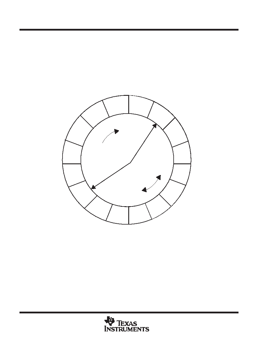
FIFO description
The FIFO is based on a circular buffer (see Figure 15, in this example the FIFO is 16 words long). The buffer is
accessed using two pointers, one for the ADC writing to the FIFO, one for the processor (DSP) reading from the buffer.
Both pointers move in a clockwise direction. If the distance between the ADC write pointer and the DSP read pointer
is greater or equal a programmable threshold, the INT signal is asserted. If this INT signal is connected to an external
interrupt pin of the processor, it is possible to read out the stored values in the FIFO at once during the interrupt service
routine. If the ADC write pointer reaches the position of the DSP read pointer, an overflow occurs. In this case, the
overflow bit in the ADC register is set and the FOVL is asserted.
7
8
9
10
11
12
13
14
15
0
1
2
3
4
5
6
ADC
DSP
T
Figure 15. Circular Buffer
相關(guān)PDF資料 |
PDF描述 |
|---|---|
| THS3001CDGNRG4 | 1 CHANNEL, VIDEO AMPLIFIER, PDSO8 |
| THS3001HVCDGN | 1 CHANNEL, VIDEO AMPLIFIER, PDSO8 |
| THS3001HVIDGNR | 1 CHANNEL, VIDEO AMPLIFIER, PDSO8 |
| THS3001HVIDGN | 1 CHANNEL, VIDEO AMPLIFIER, PDSO8 |
| THS3001IDGNG4 | 1 CHANNEL, VIDEO AMPLIFIER, PDSO8 |
相關(guān)代理商/技術(shù)參數(shù) |
參數(shù)描述 |
|---|---|
| THS14F03 | 制造商:TI 制造商全稱:Texas Instruments 功能描述:14-BIT, 1 MSPS/ 3 MSPS, DSP COMPATIBLE, ANALOG-TO-DIGITAL CONVERTERS WITH FIFO INTERNAL REFERENCE AND PGA |
| THS14F03EVM | 功能描述:數(shù)據(jù)轉(zhuǎn)換 IC 開發(fā)工具 THS14F03 Eval Mod RoHS:否 制造商:Texas Instruments 產(chǎn)品:Demonstration Kits 類型:ADC 工具用于評估:ADS130E08 接口類型:SPI 工作電源電壓:- 6 V to + 6 V |
| THS14F03IPFB | 功能描述:模數(shù)轉(zhuǎn)換器 - ADC 14-bit 3 MSPS with 32-word FIFO RoHS:否 制造商:Texas Instruments 通道數(shù)量:2 結(jié)構(gòu):Sigma-Delta 轉(zhuǎn)換速率:125 SPs to 8 KSPs 分辨率:24 bit 輸入類型:Differential 信噪比:107 dB 接口類型:SPI 工作電源電壓:1.7 V to 3.6 V, 2.7 V to 5.25 V 最大工作溫度:+ 85 C 安裝風(fēng)格:SMD/SMT 封裝 / 箱體:VQFN-32 |
| THS14F03IPFBG4 | 功能描述:模數(shù)轉(zhuǎn)換器 - ADC 14-bit 3 MSPS with 32-word FIFO RoHS:否 制造商:Texas Instruments 通道數(shù)量:2 結(jié)構(gòu):Sigma-Delta 轉(zhuǎn)換速率:125 SPs to 8 KSPs 分辨率:24 bit 輸入類型:Differential 信噪比:107 dB 接口類型:SPI 工作電源電壓:1.7 V to 3.6 V, 2.7 V to 5.25 V 最大工作溫度:+ 85 C 安裝風(fēng)格:SMD/SMT 封裝 / 箱體:VQFN-32 |
| THS14-THS18-D | 制造商:Thomas & Betts 功能描述:CATAMOUNT CABLE TIES |
發(fā)布緊急采購,3分鐘左右您將得到回復(fù)。