- 您現(xiàn)在的位置:買賣IC網(wǎng) > PDF目錄371185 > TF1004A LG1600FXH Clock and Data Regenerator PDF資料下載
參數(shù)資料
| 型號(hào): | TF1004A |
| 英文描述: | LG1600FXH Clock and Data Regenerator |
| 中文描述: | LG1600FXH時(shí)鐘和數(shù)據(jù)再生 |
| 文件頁數(shù): | 4/20頁 |
| 文件大?。?/td> | 492K |
| 代理商: | TF1004A |
Data Sheet
August 1999
LG1600FXH Clock and Data Regenerator
4
Lucent Technologies Inc.
Theory of Operation
(continued)
12-3228(F)r.4
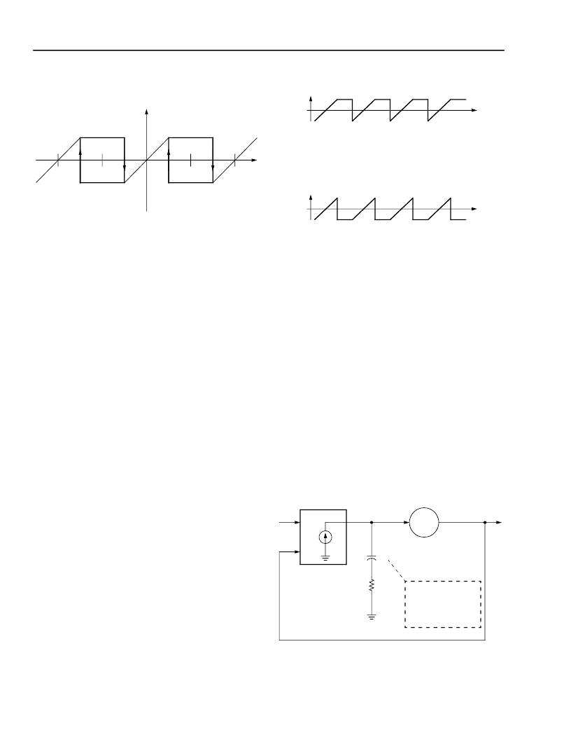
Figure 5. Frequency and Phase Detector
Characteristics
The frequency detector is not a separate function but
an integral part of the phase-lock loop. Any transition
between frequency and phase acquisition is completely
avoided. Figure 5 shows the output characteristics of
the FPD, which is essentially an extended range phase
detector. The two quadrature clock phases are used to
produce hysteresis, which extends the phase detector
range to ±270°. The extended range gives the phase
detector a static frequency sensitivity as demonstrated
in Figure 6. For clock frequencies lower than the bit rate
(the phase is increasing), the top trajectory of the dia-
gram in Figure 6 is followed. When the VCO frequency
exceeds the bit rate, the lower trajectory applies. Since
the linear part of the phase detector produces a net-
zero output, in the first instance, positive pulses are fed
into the loop filter increasing the VCO frequency, while
in the latter case, the FPD produces negative pulses.
The wide, 540° range of the phase detector is also
responsible for the high jitter tolerance of the
LG1600FXH and an associated immunity to cycle slip
under high jitter conditions. The clock can be momen-
tarily misaligned as much as 270° but still return to its
original position. This property is extremely important
in synchronous systems, since a cycle slip would cause
misalignment of the demultiplexer following the circuit
resulting in a loss of frame condition. The LG1600FXH
can handle bit error rates up to 1e
–3
as a result of low-
frequency jitter.
12-3229(F)r.4
Figure 6. Frequency Detector Operation
PLL Dimensioning
The LG1600FXH CDR employs a heavily damped
second order phase-lock loop. A linear model of this
PLL is depicted in Figure 7. The conventional second-
order equation describing the jitter transfer of the PLL
is shown below:
o
where
i
and
o
denote the input and output phase,
respectively,
is the PLL damping ratio and
ω
n
is the
natural frequency. For most clock recovery applications
a very high damping is required, that renders the PLL
essentially as a first-order system with a slight peaking
that is generally undesirable. The second-order equa-
tion above does not provide much insight into the peak-
ing and bandwidth parameters.
12-3230(F)r.5
Figure 7. Phase-Lock Loop Linear Model
–360
°
–180
°
0
°
180
°
360
°
PHASE
FPD OUT
FPD
OUT
FPD
OUT
TIME
TIME
A. fck < f
B
B. fck > f
B
H s
----- s
( )
2
ω
n
s
-----------------------------------------
ω
n
+
s
2
2
ω
n
s
ω
n
+
+
=
=
i
o
Ko
VCO
Kd
PHASE DETECTOR
SUM OF INTERNAL
AND EXTERNAL
LOOP FILTER
CAPACITANCE
C
Rx
相關(guān)PDF資料 |
PDF描述 |
|---|---|
| TF1006A | LG1625AXF Laser Driver |
| TFA9841J | 1-channel audio amplifier |
| TFA9843J | 2-channel audio amplifier (SE: 1 W to 20 W or BTL: 4 W to 40 W) |
| TFDS3000 | CONNECTOR ACCESSORY |
| TFMS5560 | Photo Modules for PCM Remote Control Systems |
相關(guān)代理商/技術(shù)參數(shù) |
參數(shù)描述 |
|---|---|
| TF100-5 | 制造商:RHOMBUS-IND 制造商全稱:Rhombus Industries Inc. 功能描述:TF Series High Performance 20 Section 10-Tap Delay Lines / SP3 Series |
| TF100505 | 制造商:FRONTIER 制造商全稱:Frontier Electronics. 功能描述:Tape and Reel Specifications |
| TF100505-10NJ | 制造商:FRONTIER 制造商全稱:Frontier Electronics. 功能描述:Multi-layers Chip Inductors |
| TF100505-10NK | 制造商:FRONTIER 制造商全稱:Frontier Electronics. 功能描述:Multi-layers Chip Inductors |
| TF100505-12NJ | 制造商:FRONTIER 制造商全稱:Frontier Electronics. 功能描述:Multi-layers Chip Inductors |
發(fā)布緊急采購,3分鐘左右您將得到回復(fù)。