- 您現(xiàn)在的位置:買(mǎi)賣(mài)IC網(wǎng) > PDF目錄383939 > TDA4474 Multistandard Video-IF and Quasi Parallel Sound Processing PDF資料下載
參數(shù)資料
| 型號(hào): | TDA4474 |
| 英文描述: | Multistandard Video-IF and Quasi Parallel Sound Processing |
| 中文描述: | 多標(biāo)準(zhǔn)視頻中頻和準(zhǔn)并行聲音處理 |
| 文件頁(yè)數(shù): | 5/18頁(yè) |
| 文件大?。?/td> | 295K |
| 代理商: | TDA4474 |
第1頁(yè)第2頁(yè)第3頁(yè)第4頁(yè)當(dāng)前第5頁(yè)第6頁(yè)第7頁(yè)第8頁(yè)第9頁(yè)第10頁(yè)第11頁(yè)第12頁(yè)第13頁(yè)第14頁(yè)第15頁(yè)第16頁(yè)第17頁(yè)第18頁(yè)
TELEFUNKEN Semiconductors
TDA4474
Preliminary Information
Rev. A1: 17.08.1995
5 (17)
SIF amplifier output is multiplied in phase with the
limited SIF signal (AM is removed). The AF signal of the
demodulator output is fed to the output amplifier and to
the SIF–AGC. For all TV standards with negative video
modulation (e.g. B/G standard) the AF output signal
(Pin 27) is switched off by the standard switch.
Quasi–Parallel–Sound (QPS) mixer
The QPS mixer is realized by a multiplier. The SIF signal
(FM or NICAM carrier) is converted to the intercarrier
frequency by the regenerated picture carrier (quadrature
signal) which is provided from the VCO. The intercarrier
signal is fed via an output amplifier to Pin 26.
Standard Switch
To have equal polarity of the video output signal the
polarity can be switched in the demodulation stage in
accordance with the TV standard. Additional a standard
dependent DC level shift in the video amplifier delievers
the same sync level. Parallel the correct VIF–AGC is
selected for positive or negative modulated VIF signals.
In case of negative modulation (e.g. B/G standard) the
AM output signal is switched off. If the standard for
positive modulation (L standard) is selected the AM
demodulator and QPS mixer is active. This condition
allows a parallel operation of the AM sound signal and the
NICAM–L stereo sound.
L’ Switch and VIF Input Selection
For positive modulated signals (L/L’ standard) Pin 16
works as L’ switch. With a control voltage the VCO
frequency can be switched for setting to the required
L’ value (L’ standard). Also a fine adjustment of the
L’-VCO centre frequency is possible by a potentiometer.
The L’ switch is only active for positive modulated video
IF signals (standard switch in L mode). In this mode the
video IF input 2 (VIF2) is forced by the standard switch.
The possibility to select VIF1 input is given by
connecting VIF2 input (Pin 10 or 11) via 10 k resistor to
ground.
If negative modulation (B/G mode) is selected pin 16 op-
erates as an input selection switch for the two VIF inputs.
AFC Switch
The AFC output signal at Pin 24 can be controlled by a
switching voltage at Pin 21. It is possible to select an AFC
output signal with rising– or falling AFC curve and to
switch off the AFC.
Internal Voltage Stabilizer
The internal bandgap reference ensures constant
performance independant of supply voltage and
temperature.
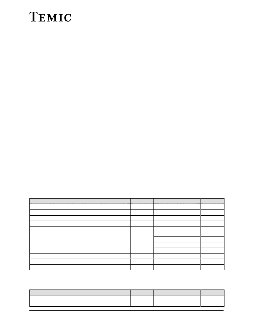
Absolute maximum values
Reference point pin 4 (9, 18), unless otherwise specified
Parameters
Symbol
V
s
I
s
out
Value
9.0
85
Unit
V
mA
áááááááááááááááááááááááááááááá
Supply voltage
Supply current
á
áááááááááááááááááááááááááááááá
áááááááááááááááááááááááááááááá
áááááááááááááááááááááááááááááá
*) Equivalent to discharging a 200 pF capacitor through a 0 resistor
áááááááááááááááááááááááááááááá
s
External voltages
Pin 25
Pin 25
ááá
junc
stor
+ 13.5
V
s
áááááá
V
V
ááá
áááááááááááááááááááááááááááááá
áááááááááááááááááááááááááááááá
áááááááááááááááááááááááááááááá
áááááááááááááááááááááááááááááá
Pins 1, 2, 5–8, 10–12,
14, 16, 19, 20, 26–30
Pin 13
Pins 3, 15, 21, 24
á
á
á
á
áááááááááááááááááááááááááááááá
áááááááááááááááááááááááááááááá
Operating Range
Parameters
Symbol
Value
Unit
áááááááááááááááááááááááááááááá
áááááááááááááááááááááááááááááá
áááááááááááááááááááááááááááááá
相關(guān)PDF資料 |
PDF描述 |
|---|---|
| TDA4655 | Generic multi-standard decoder |
| TDA4655T | Generic multi-standard decoder |
| TDA4657 | Generic multi-standard decoder |
| TDA4657T | DIODE SCHOTTKY 30V 30A TO220AB |
| TDA4662 | DIODE SCHOTTKY 60V 30A TO247AC |
相關(guān)代理商/技術(shù)參數(shù) |
參數(shù)描述 |
|---|---|
| TDA44750-4008 | 制造商:ITT Interconnect Solutions 功能描述:E-SYS #016-01543-001 - Bulk |
| TDA44750-4044 | 制造商:ITT Interconnect Solutions 功能描述:OBS-TDA15P1C4 W/CL. NUT - Bulk |
| TDA4480C | 制造商:TEMIC 制造商全稱(chēng):TEMIC Semiconductors 功能描述:Multi standard quasi parallel-sound processor for TV-sets |
| TDA4480-C | 制造商:TEMIC 制造商全稱(chēng):TEMIC Semiconductors 功能描述:Multi standard quasi parallel-sound processor for TV-sets |
| TDA4480D | 制造商:未知廠家 制造商全稱(chēng):未知廠家 功能描述:Consumer IC |
發(fā)布緊急采購(gòu),3分鐘左右您將得到回復(fù)。