- 您現(xiàn)在的位置:買賣IC網(wǎng) > PDF目錄383935 > TCM38C17 (Intersil Corporation) () PDF資料下載
參數(shù)資料
| 型號(hào): | TCM38C17 |
| 廠商: | Intersil Corporation |
| 英文描述: | () |
| 中文描述: | () |
| 文件頁數(shù): | 1/7頁 |
| 文件大小: | 106K |
| 代理商: | TCM38C17 |
4-1
TM
AN9852.1
1-888-INTERSIL or 321-724-7143
|
Intersil and Design is a trademark of Intersil Corporation.
|
Copyright
Intersil Corporation 2000
TCM38C17 Quad Combo Interface to HC55181
and HC5503
Introduction
The TCM38C17 is a four-channel PCM combo. The term
combo implies a CODEC and filters. This means that in
addition to the ADC and DAC, the antialiasing filter and the
smoothing filters are also on the chip. The TCM38C17
complies with CCITT/(D3/D4) G.711 and G.714 Channel
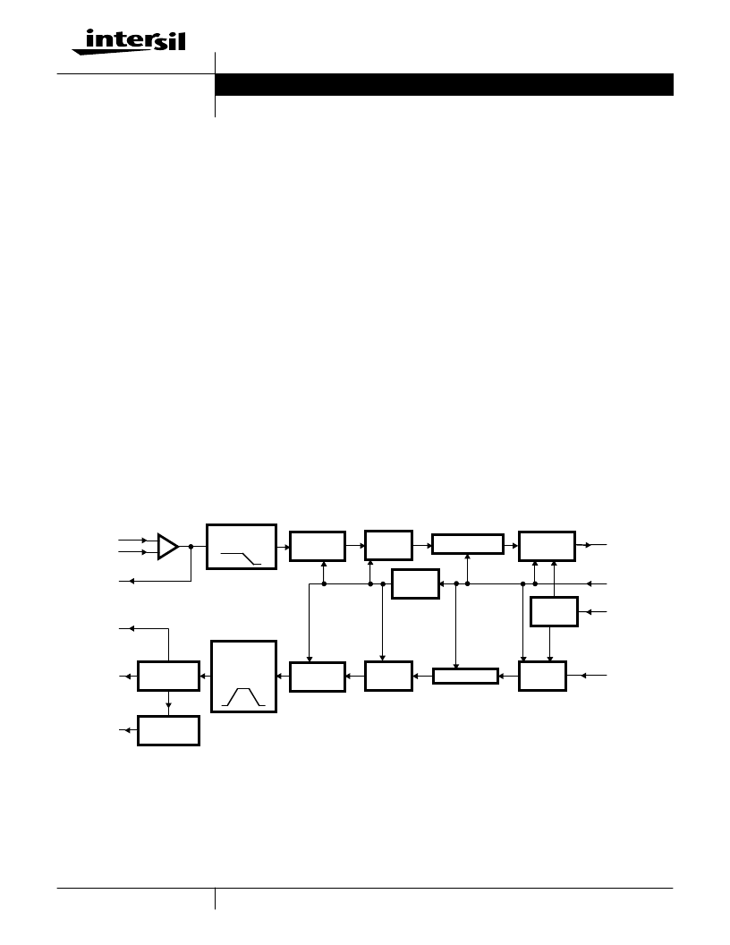
Bank Specifications. [1] Figure 1 shows the block diagram of
a single TCM38C17 channel.
The TCM38C17 uses sigma-delta converter technology and
provides the option of selecting A-Law or
μ
-Law
companding. It has a single PCM I/O for a simplified PCM
interface. Each channel can interface a full-duplex, 4-line
voice telephone circuit with a time-division-multiplexed
system. The crosstalk between channels is less than
-100dB, which means that the TCM38C17 saves board
space without any crosstalk. The TCM38C17 provides
8V
P-P
full-signal differential receiver output.
These parts typically are used in line card applications. The
major components on a line card include a combo, SLIC,
microcontroller, voltage regulators, and transient voltage
suppressors. The SLIC, in addition to other things, converts
the analog signal from two-wire to four-wire and vice-versa.
In this process, some of the signal applied at the receive
channel of the SLIC appears at the transmit channel,
deteriorating voice quality. This would result in the person
hearing his own voice back through the handset. To reduce
this effect, a transhybrid balance circuit is used between the
combo and the SLIC. The transhybrid balance circuitry given
below provides some degree of isolation, but for better
performance, the transhybrid must include op amps.
TCM38C17 Interface to the HC5503 SLIC
This section gives details on interfacing the TCM38C17 with
HC5503 SLIC. The test setup consists of:
HC5503 SLIC Evaluation Board
TCM38C17 Test Board
Bread board to implement the transhybrid circuitry
Figure 2 shows the test setup to measure how much of the
signal appears at test point 3 when a signal is applied at test
point 2.
The transhybrid circuitry given does not use on op amp.
Instead, it consists only of resistors and capacitors. The
amplifier forms the input stage of the TCM38C17. Some of
the specifications of this amplifier are given in Table A-1 in
the Appendix.
FIGURE 1. BLOCK DIAGRAM OF A TCM38C17 CHANNEL
OUTPUT
REGISTER
Σ
ADC
+
-
Σ
DAC
OUTPUT
AMPLIFIER
INVERTING
AMPLIFIER
ANGLIN+
GSX
GSR
PWRO+
PWRO-
ANGLIN-
INPUT
REGISTER
PCMOUT
MCLK
(2.048MHz)
FS
PCMIN
FRAME
CONTROL
COMPRESSOR
EXPANDER
CLOCK
BUFFER
DIGITAL
FILTER
DIGITAL
FILTER
ANTIALIAS
FILTER
SWITCHED-
CAPACITOR
SMOOTHING
FILTER
Application Note
March 2000
Author: Ziad Asghar (Texas Instruments)
相關(guān)PDF資料 |
PDF描述 |
|---|---|
| TCM809JELB713 | 3-Pin Microcontroller Reset Monitors |
| TCM809JENB713 | 3-Pin Microcontroller Reset Monitors |
| TCM809JVLB713 | 3-Pin Microcontroller Reset Monitors |
| TCM809JVNB713 | 3-Pin Microcontroller Reset Monitors |
| TCM809LELB713 | 3-Pin Microcontroller Reset Monitors |
相關(guān)代理商/技術(shù)參數(shù) |
參數(shù)描述 |
|---|---|
| TCM38C17IDL | 功能描述:接口—CODEC Quad PCM Combo RoHS:否 制造商:Texas Instruments 類型: 分辨率: 轉(zhuǎn)換速率:48 kSPs 接口類型:I2C ADC 數(shù)量:2 DAC 數(shù)量:4 工作電源電壓:1.8 V, 2.1 V, 2.3 V to 5.5 V 最大工作溫度:+ 85 C 安裝風(fēng)格:SMD/SMT 封裝 / 箱體:DSBGA-81 封裝:Reel |
| TCM38C17IDLDL | 制造商:TI 制造商全稱:Texas Instruments 功能描述:QComboE FOUR-CHANNEL QUAD PCM COMBO |
| TCM38C17IDLR | 制造商:Texas Instruments 功能描述:Audio Codec 1ADC / 1DAC 48-Pin SSOP T/R |
| TCM4110 | 制造商:TI 制造商全稱:Texas Instruments 功能描述:PCM U-LOW COMPANDING CODES |
| TCM4205J4 | 制造商:Texas Instruments 功能描述: |
發(fā)布緊急采購,3分鐘左右您將得到回復(fù)。