- 您現(xiàn)在的位置:買賣IC網(wǎng) > PDF目錄98181 > TC820CLW 1-CH DUAL-SLOPE ADC, PQCC44 PDF資料下載
參數(shù)資料
| 型號(hào): | TC820CLW |
| 元件分類: | ADC |
| 英文描述: | 1-CH DUAL-SLOPE ADC, PQCC44 |
| 封裝: | PLASTIC, LCC-44 |
| 文件頁數(shù): | 9/24頁 |
| 文件大?。?/td> | 185K |
| 代理商: | TC820CLW |

17
TC820
3-3/4 A/D Converter with Frequency
Counter and Logic Probe
TC820-10 10/17/96
2001 Microchip Technology Inc.
DS21476A
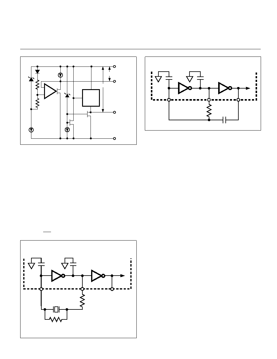
Figure 15. Suggested Crystal Oscillator Circuit
5pF
37
38
39
110k
10pF
75pF
TC820
Figure 14. DGND and COM Outputs
+
–
12
A
P
TC820
LOGIC
SECTION
5V
3.2V
N
VDD
VSS
COM
DGND
Figure 16. R-C Oscillator Circuit
Typical values are R = 10k
and C = 68pF. The resis-
tor value should be
≥100k. For accurate frequency mea-
surement, an R-C oscillator frequency of 40kHz is re-
quired.
System Timing
All system timing is derived from the clock oscillator.
The clock oscillator is divided by 2 prior to clocking the A/D
counters. The clock is also divided by 8 to drive the buzzer,
by 240 to generate the LCD backplane frequency, and by
40,000 for the frequency counter time base. A simplified
diagram of the system clock is shown in Figure 17.
Component Value Selection
Auto Zero Capacitor — CAZ
The value of the auto-zero capacitor (CAZ) has some
influence on system noise. A 0.47
F capacitor is recom-
mended; a low dielectric absorption capacitor (Mylar) is
required.
Reference Voltage Capacitor — CREF
The reference voltage capacitor used to ramp the inte-
grator output voltage back to zero during the reference
integrate cycle is stored on CREF. A 0.1F capacitor is
typical. A good quality, low leakage capacitor (such as
Mylar) should be used.
Integrating Capacitor — CINT
CINT should be selected to maximize integrator output
voltage swing without causing output saturation. Analog
common will normally supply the differential voltage
reference. For this case, a
±2V integrator output swing is
optimum when the analog input is near full scale. For 2.5
readings/second (fOSC = 40kHz) and VFS = 400mV, a
0.22
F value is suggested. If a different oscillator frequency
is used, CINT must be changed in inverse proportion to
0.3
RC
Clock Oscillator
The TC820 oscillator can be controlled with either a
crystal or with an inexpensive resistor-capacitor combina-
tion. The crystal circuit, shown in Figure 15, is recom-
mended when high accuracy is required in the frequency
counter mode. The 40kHz crystal is a standard frequency
for ultrasonic alarms, and will provide a 1-second time
base for the counter or 2.5 analog-to-digital conversions
per second. Consult the crystal manufacturer for detailed
applications information.
Where low cost is important, the R-C circuit of Figure
16 can be used. The frequency of this circuit will be
approximately:
fOSC =
TC820
40kHz
38
39
5 pF
10pF
22 M
470k
37
相關(guān)PDF資料 |
PDF描述 |
|---|---|
| TC820CKW | 1-CH DUAL-SLOPE ADC, PQFP44 |
| TC823CKW | CONVERTER SUBSYSTEM ADC, PARALLEL ACCESS, PQFP44 |
| TC823EKW | CONVERTER SUBSYSTEM ADC, PARALLEL ACCESS, PQFP44 |
| TC823ELW | CONVERTER SUBSYSTEM ADC, PARALLEL ACCESS, PQCC44 |
| TC823EPL | CONVERTER SUBSYSTEM ADC, PARALLEL ACCESS, PDIP40 |
相關(guān)代理商/技術(shù)參數(shù) |
參數(shù)描述 |
|---|---|
| TC820CLW713 | 功能描述:LCD 驅(qū)動(dòng)器 3-3/4 A/D Converter RoHS:否 制造商:Maxim Integrated 數(shù)位數(shù)量:4.5 片段數(shù)量:30 最大時(shí)鐘頻率:19 KHz 工作電源電壓:3 V to 3.6 V 最大工作溫度:+ 85 C 最小工作溫度:- 20 C 封裝 / 箱體:PDIP-40 封裝:Tube |
| TC820CPL | 功能描述:LCD 驅(qū)動(dòng)器 3-3/4 A/D Converter RoHS:否 制造商:Maxim Integrated 數(shù)位數(shù)量:4.5 片段數(shù)量:30 最大時(shí)鐘頻率:19 KHz 工作電源電壓:3 V to 3.6 V 最大工作溫度:+ 85 C 最小工作溫度:- 20 C 封裝 / 箱體:PDIP-40 封裝:Tube |
| TC8-20S2405R | 制造商:TRUMPOWER 制造商全稱:Tumbler Technologies + TRUMPower 功能描述:DC/DC CONVERTERS 2:1 Input, 12.5 to 20 Watt |
| TC8-20S4805R | 制造商:TRUMPOWER 制造商全稱:Tumbler Technologies + TRUMPower 功能描述:DC/DC CONVERTERS 2:1 Input, 12.5 to 20 Watt |
| TC-821-SC | 制造商:Thomas & Betts 功能描述:Cable Accessories Thin Wall Conduit Fitting Zinc Die Cast |
發(fā)布緊急采購(gòu),3分鐘左右您將得到回復(fù)。