- 您現(xiàn)在的位置:買賣IC網(wǎng) > PDF目錄383931 > TC648VOA (Microchip Technology Inc.) Fan Speed Controller with Auto-Shutdown and Over-Temperature Alert PDF資料下載
參數(shù)資料
| 型號(hào): | TC648VOA |
| 廠商: | Microchip Technology Inc. |
| 英文描述: | Fan Speed Controller with Auto-Shutdown and Over-Temperature Alert |
| 中文描述: | 與自動(dòng)風(fēng)扇轉(zhuǎn)速控制關(guān)斷和過溫警報(bào) |
| 文件頁數(shù): | 12/28頁 |
| 文件大小: | 602K |
| 代理商: | TC648VOA |
第1頁第2頁第3頁第4頁第5頁第6頁第7頁第8頁第9頁第10頁第11頁當(dāng)前第12頁第13頁第14頁第15頁第16頁第17頁第18頁第19頁第20頁第21頁第22頁第23頁第24頁第25頁第26頁第27頁第28頁
TC648
DS21448C-page 12
2002 Microchip Technology Inc.
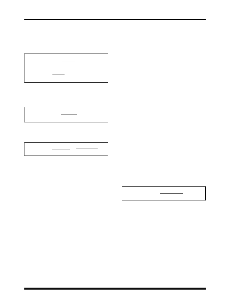
Per Section 1.0, “Electrical Characteristics”, the leak-
age current at the V
AS
pin is no more than 1 μA. It is
conservative to design for a divider current, I
DIV
, of
100 μA. If V
DD
= 5.0V then…
EQUATION
We can further specify R
1
and R
2
by the condition that
the divider voltage is equal to our desired V
AS
. This
yields the following:
EQUATION
Solving for the relationship between R
1
and R
2
results
in the following equation:
EQUATION
For this example, R
1
= (2.27) R
2
. Substituting this rela-
tionship back into the original equation yields the
resistor values:
R
2
= 15.3 k
, and R
1
= 34.7 k
In this case, the standard values of 34.8 k
and
15.4 k
are very close to the calculated values and
would be more than adequate.
5.4
Output Drive Transistor Selection
The TC648 is designed to drive an external transistor
or MOSFET for modulating power to the fan. This is
shown as Q
1
in Figures 5-1, 5-6, 5-7,and 5-8. The
V
OUT
pin has a minimum source current of 5 mA and a
minimum sink current of 1 mA. Bipolar transistors or
MOSFETs may be used as the power switching ele-
ment, as is shown in Figure 5-6. When high current
gain is needed to drive larger fans, two transistors may
be used in a Darlington configuration. These circuit
topologies are shown in Figure 5-6: (a) shows a single
NPN transistor used as the switching element; (b) illus-
trates the Darlington pair; and (c) shows an N-channel
MOSFET.
One major advantage of the TC648’s PWM control
scheme versus linear speed control is that the power
dissipation in the pass element is kept very low.
Generally, low cost devices in very small packages,
such as TO-92 or SOT, can be used effectively. For
fans with nominal operating currents of no more than
200 mA, a single transistor usually suffices. Above
200 mA, the Darlington or MOSFET solution is
recommended. For the power dissipation to be kept
low, it is imperative that the pass transistor be fully sat-
urated when "on".
Table 5-1 gives examples of some commonly available
transistors and MOSFETs. This table should be used
as a guide only since there are many transistors and
MOSFETs which will work just as well as those listed.
The critical issues when choosing a device to use as
Q1 are: (1) the breakdown voltage (V
(BR)CEO
or V
DS
(MOSFET)) must be large enough to withstand the
highest voltage applied to the fan (
Note:
This will occur
when the fan is off); (2) 5 mA of base drive current must
be enough to saturate the transistor when conducting
the full fan current (transistor must have sufficient
gain); (3) the V
OUT
voltage must be high enough to suf-
ficiently drive the gate of the MOSFET to minimize the
R
DS(on)
of the device; (4) rated fan current draw must
be within the transistor's/MOSFET's current handling
capability; and (5) power dissipation must be kept
within the limits of the chosen device.
A base-current limiting resistor is required with bipolar
transistors. The correct value for this resistor can be
determined as follows:
V
OH
V
RBASE
= R
BASE
x I
BASE
I
BASE
= I
FAN
/ h
FE
= V
BE(SAT)
+ V
RBASE
V
OH
is specified as 80% of V
DD
in Section 1.0,
“Electrical Characteristics”; V
BE(SAT)
is given in the
chosen transistor data sheet. It is now possible to solve
for R
BASE
.
EQUATION
Some applications benefit from the fan being powered
from a negative supply to keep motor noise out of the
positive supply rails. This can be accomplished by the
method shown in Figure 5-7. Zener diode D
1
offsets
the -12V power supply voltage, holding transistor Q
1
off
when V
OUT
is low. When V
OUT
is high, the voltage at
the anode of D
1
increases by V
OH
, causing Q
1
to turn
on. Operation is otherwise the same as in the case of
fan operation from +12V.
R
1
+ R
2
I
DIV
= 1e
–4
A = 5.0V
, therefore
R
1
+ R
2
= 5.0V
= 50 k
1e
–4
A
V
DD
x R
2
R
1
+ R
2
V
AS
=
V
DD
- V
AS
V
AS
R
1
= R
2
x
=
R
2
x (5 - 1.53)
1.53
V
OH
- V
BE(SAT)
I
BASE
R
BASE
=
相關(guān)PDF資料 |
PDF描述 |
|---|---|
| TC648 | Fan Speed Controller with Auto-Shutdown and Over-Temperature Alert |
| TC648E | Fan Speed Controller with Auto-Shutdown and Over-Temperature Alert |
| TC648VPA | Fan Speed Controller with Auto-Shutdown and Over-Temperature Alert |
| TC649EOA | PWM Fan Speed Controller with Auto-Shutdown and FanSense⑩ Technology |
| TC649VOA | CAPACITOR, CLASS Y2 15NFCAPACITOR, CLASS Y2 15NF; Capacitance:15nF; Voltage rating, AC:250V; Voltage rating, DC:2500V; Capacitor dielectric type:Polypropylene; Series:B81122; Tolerance, +:20%; Tolerance, -:20%; Temp, op. |
相關(guān)代理商/技術(shù)參數(shù) |
參數(shù)描述 |
|---|---|
| TC648VOA | 制造商:Microchip Technology Inc 功能描述:Fan Management Controller IC Package/Cas |
| TC648VOA713 | 功能描述:馬達(dá)/運(yùn)動(dòng)/點(diǎn)火控制器和驅(qū)動(dòng)器 Shtdn & Over-T Alert RoHS:否 制造商:STMicroelectronics 產(chǎn)品:Stepper Motor Controllers / Drivers 類型:2 Phase Stepper Motor Driver 工作電源電壓:8 V to 45 V 電源電流:0.5 mA 工作溫度:- 25 C to + 125 C 安裝風(fēng)格:SMD/SMT 封裝 / 箱體:HTSSOP-28 封裝:Tube |
| TC648VPA | 功能描述:馬達(dá)/運(yùn)動(dòng)/點(diǎn)火控制器和驅(qū)動(dòng)器 Shtdn & Over-T Alert RoHS:否 制造商:STMicroelectronics 產(chǎn)品:Stepper Motor Controllers / Drivers 類型:2 Phase Stepper Motor Driver 工作電源電壓:8 V to 45 V 電源電流:0.5 mA 工作溫度:- 25 C to + 125 C 安裝風(fēng)格:SMD/SMT 封裝 / 箱體:HTSSOP-28 封裝:Tube |
| TC648VPA | 制造商:Microchip Technology Inc 功能描述:Fan Management Controller IC |
| TC648VUA | 功能描述:馬達(dá)/運(yùn)動(dòng)/點(diǎn)火控制器和驅(qū)動(dòng)器 Shtdn & Over-T Alert RoHS:否 制造商:STMicroelectronics 產(chǎn)品:Stepper Motor Controllers / Drivers 類型:2 Phase Stepper Motor Driver 工作電源電壓:8 V to 45 V 電源電流:0.5 mA 工作溫度:- 25 C to + 125 C 安裝風(fēng)格:SMD/SMT 封裝 / 箱體:HTSSOP-28 封裝:Tube |
發(fā)布緊急采購,3分鐘左右您將得到回復(fù)。