- 您現(xiàn)在的位置:買賣IC網(wǎng) > PDF目錄383928 > TC3405A (Linear Technology Corporation) Standalone Linear Li-lon Battery Charger with Thermistor Input PDF資料下載
參數(shù)資料
| 型號: | TC3405A |
| 廠商: | Linear Technology Corporation |
| 元件分類: | 熱敏電阻 |
| 英文描述: | Standalone Linear Li-lon Battery Charger with Thermistor Input |
| 中文描述: | 獨立線性鋰離子電池充電器熱敏電阻輸入 |
| 文件頁數(shù): | 12/20頁 |
| 文件大?。?/td> | 665K |
| 代理商: | TC3405A |
LTC4061
12
4061fa
+
V
CC
C/5
CHRG
PROG
I
DET
C
0.1μF
V
IN
4061 F02
BAT
500mA
TIMER
R
DET
1k
R
PROG
2k
LTC4061
GND
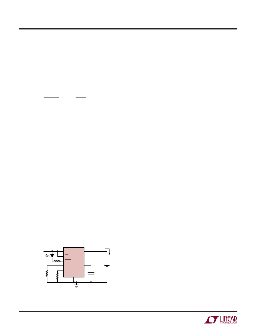
Figure 2. Time Termination Mode.
The Charge Cycle Ends After 3 Hours.
When the programmed time has elapsed, the charge
cycle terminates and the charger enters standby mode.
Subsequent recharge cycles terminate when 50% of the
programmed time has elapsed. The I
DET
pin determines
the behavior of the
C
H
R
G output. Connecting a resistor
(R
DET
) from the I
DET
pin to ground sets the charge current
detection threshold, I
DETECT
:
I
R
10
100
R
V
I
V
R
or
R
I
DETECT
PROG
DET
CHG
DET
DET
DETECT
=
=
=
100
When the charge current (I
BAT
) is greater than
I
DETECT
, the
C
H
R
G output is in its pull-down state. When
the charger enters constant voltage mode operation and
the charge current falls below I
DETECT
, the
C
H
R
G output
becomes high impedance, indicating that the battery is
almost fully charged. The
C
H
R
G output will also become
high impedance once the charge time elapses. If the I
DET
pin is not connected, the
C
H
R
G output remains in its pull-
down state until the charge time elapses and terminates
the charge cycle.
Figure 2 shows a charger circuit using charge time termi-
nation that is programmed to charge at 500mA. Once the
charge current drops below 100mA in constant voltage
mode (as set by R
DET
), the
C
H
R
G output turns off the
LED. This indicates to the user that the battery is almost
fully charged and ready to use. The LTC4061 continues
to charge the battery until the internal timer reaches 3
hours (as set by C
TIMER
). During recharge cycles, the
LTC4061 charges the battery until the internal timer reaches
1.5 hours. Figure 3 describes the operation of the LTC4061
charger when charge time termination is used.
Charge Current Termination
Connecting the TIMER pin to ground selects charge cur-
rent termination. With this method, the timer is disabled
and a resistor (R
DET
) must be connected from the I
DET
pin to ground. I
DETECT
is programmed using the same
equation stated in the previous section. The charge cycle
terminates when the charge current falls below I
DETECT
.
This condition is detected using an internal filtered
comparator to monitor the I
DET
pin. When the I
DET
pin
falls below 100mV for longer than t
TERM
(typically 1ms),
charging is terminated.
When charging, transient loads on the BAT pin can cause
the I
DET
pin to fall below 100mV for short periods of time
before the DC current has dropped below the I
DETECT
threshold. The 1.5ms filter time (t
TERM
) on the internal
comparator ensures that transient loads of this nature do
not result in premature charge cycle termination. Once the
average
charge current drops below I
DETECT
, the charger
terminates the charge cycle.
The
C
H
R
G output is in a pull-down state while charging
and in a high impedance state once charging has stopped.
Figure 4 describes the operation of the LTC4061 charger
when charge current termination is used.
User-Selectable Charge Termination
Connecting the TIMER pin to V
CC
selects user-selectable
charge termination, in which all of the internal termination
features are disabled. The charge cycle continues indefi-
nitely until the charger is shut down through the
E
N pin.
The I
DET
pin programs the behavior of the
C
H
R
G output in
the same manner as when using charge time termination.
If the I
DET
pin is not connected, the
C
H
R
G output remains
in its pull-down state until the charger is shut down.
With user-selectable charge termination, the SmartStart
feature is disabled; when the charger is powered on or
enabled, the LTC4061 automatically begins charging,
regardless of the battery voltage. Figure 5 describes
charger operation when user-selectable charge termina-
tion is used.
APPLICATIOU
W
U
U
相關(guān)PDF資料 |
PDF描述 |
|---|---|
| TC3405VQR | 16-Bit, Low Cost, Low Power Sigma-Delta A/D Converter |
| TC3405VPE | 16-Bit, Low Cost, Low Power Sigma-Delta A/D Converter |
| TC3405 | 16-Bit, Low Cost, Low Power Sigma-Delta A/D Converter |
| TC4420IMF713 | 6A High-Speed MOSFET Drivers |
| TC4420IOA | 6A High-Speed MOSFET Drivers |
相關(guān)代理商/技術(shù)參數(shù) |
參數(shù)描述 |
|---|---|
| TC3405VPE | 功能描述:模數(shù)轉(zhuǎn)換器 - ADC 16-Bit Sigma-Delta RoHS:否 制造商:Texas Instruments 通道數(shù)量:2 結(jié)構(gòu):Sigma-Delta 轉(zhuǎn)換速率:125 SPs to 8 KSPs 分辨率:24 bit 輸入類型:Differential 信噪比:107 dB 接口類型:SPI 工作電源電壓:1.7 V to 3.6 V, 2.7 V to 5.25 V 最大工作溫度:+ 85 C 安裝風(fēng)格:SMD/SMT 封裝 / 箱體:VQFN-32 |
| TC3405VQR | 功能描述:模數(shù)轉(zhuǎn)換器 - ADC 16-Bit Sigma-Delta RoHS:否 制造商:Texas Instruments 通道數(shù)量:2 結(jié)構(gòu):Sigma-Delta 轉(zhuǎn)換速率:125 SPs to 8 KSPs 分辨率:24 bit 輸入類型:Differential 信噪比:107 dB 接口類型:SPI 工作電源電壓:1.7 V to 3.6 V, 2.7 V to 5.25 V 最大工作溫度:+ 85 C 安裝風(fēng)格:SMD/SMT 封裝 / 箱體:VQFN-32 |
| TC3405VQRTR | 功能描述:模數(shù)轉(zhuǎn)換器 - ADC 16-Bit Sigma-Delta RoHS:否 制造商:Texas Instruments 通道數(shù)量:2 結(jié)構(gòu):Sigma-Delta 轉(zhuǎn)換速率:125 SPs to 8 KSPs 分辨率:24 bit 輸入類型:Differential 信噪比:107 dB 接口類型:SPI 工作電源電壓:1.7 V to 3.6 V, 2.7 V to 5.25 V 最大工作溫度:+ 85 C 安裝風(fēng)格:SMD/SMT 封裝 / 箱體:VQFN-32 |
| TC341 | 制造商:TI 制造商全稱:Texas Instruments 功能描述:780X488 PIXEL CCD IMAGE SENSOR |
| TC341-20 | 功能描述:視頻 IC 780 X 488-Pixel CCD Image Sensor RoHS:否 制造商:Fairchild Semiconductor 工作電源電壓:5 V 電源電流:80 mA 最大工作溫度:+ 85 C 封裝 / 箱體:TSSOP-28 封裝:Reel |
發(fā)布緊急采購,3分鐘左右您將得到回復(fù)。