- 您現(xiàn)在的位置:買賣IC網(wǎng) > PDF目錄383890 > TC1303A-AQ2EUN (Microchip Technology Inc.) 500 mA Synchronous Buck Regulator, + 300 mA LDO with Power-Good Output PDF資料下載
參數(shù)資料
| 型號(hào): | TC1303A-AQ2EUN |
| 廠商: | Microchip Technology Inc. |
| 英文描述: | 500 mA Synchronous Buck Regulator, + 300 mA LDO with Power-Good Output |
| 中文描述: | 500毫安同步降壓穩(wěn)壓器,300 mA的LDO具有電源就緒輸出 |
| 文件頁數(shù): | 24/36頁 |
| 文件大?。?/td> | 463K |
| 代理商: | TC1303A-AQ2EUN |
第1頁第2頁第3頁第4頁第5頁第6頁第7頁第8頁第9頁第10頁第11頁第12頁第13頁第14頁第15頁第16頁第17頁第18頁第19頁第20頁第21頁第22頁第23頁當(dāng)前第24頁第25頁第26頁第27頁第28頁第29頁第30頁第31頁第32頁第33頁第34頁第35頁第36頁
TC1303A/TC1303B/TC1303C/TC1304
DS21949B-page 24
2005 Microchip Technology Inc.
5.5
Inductor Selection
For most applications, a 4.7 μH inductor is recom-
mended to minimize noise. There are many different
magnetic core materials and package options to select
from. That decision is based on size, cost and accept-
able radiated energy levels. Toroid and shielded ferrite
pot cores will have low radiated energy, but tend to be
larger and higher is cost. With a typical 2.0 MHz switch-
ing frequency, the inductor ripple current can be
calculated based on the following formulas.
EQUATION 5-2:
Duty cycle represents the percentage of switch-on
time.
EQUATION 5-3:
The inductor ac ripple current can be calculated using
the following relationship:
EQUATION 5-4:
Solving for
Δ
I
L
= yields:
EQUATION 5-5:
When considering inductor ratings, the maximum DC
current rating of the inductor should be at least equal to
the maximum buck regulator load current (I
OUT1
), plus
one half of the peak-to-peak inductor ripple current
(1/2 *
Δ
I
L
). The inductor DC resistance can add to the
buck converter I
2
R losses. A rating of less than 200 m
Ω
is recommended. Overall efficiency will be improved by
using lower DC resistance inductors.
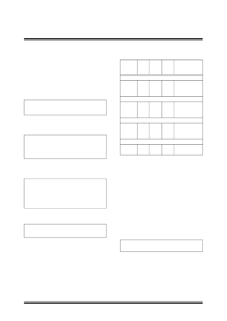
TABLE 5-2:
TC1303A, TC1303B, TC1303C,
TC1304 RECOMMENDED
INDUCTOR VALUES
5.6
Thermal Calculations
5.6.1
BUCK REGULATOR OUTPUT
(V
OUT1
)
The TC1303/TC1304 is available in two different 10-pin
packages (MSOP and 3X3 DFN). By calculating the
power dissipation and applying the package thermal
resistance, (
θ
JA
), the junction temperature is estimated.
The maximum continuous junction temperature rating
for the TC1303/TC1304 is +125°C.
To quickly estimate the internal power dissipation for
the switching buck regulator, an empirical calculation
using measured efficiency can be used. Given the
measured efficiency (
Section 2.0 “Typical Perfor-
mance Curves”
), the internal power dissipation is
estimated below:
EQUATION 5-6:
V
Efficiency
The first term is equal to the input power (definition of
efficiency, P
OUT
/P
IN
=
Efficiency). The second term is
equal to the delivered power. The difference is internal
power dissipation. This is an estimate assuming that
most of the power lost is internal to the TC1303B.
There is some percentage of power lost in the buck
inductor, with very little loss in the input and output
capacitors.
DutyCycle
V
V
IN
-------------
=
T
ON
DutyCycle
F
SW
---------
×
=
Where:
F
SW
= Switching Frequency.
V
L
L
Δ
I
L
t
--------
×
=
Where:
V
L
= voltage across the inductor (V
IN
– V
OUT
)
Δ
t = on-time of P-channel MOSFET
Δ
I
L
V
L
L
-----
Δ
t
×
=
Part
Number
Value
(μH)
DCR
Ω
(
MAX)
MAX
I
DC
(A)
Size
WxLxH (mm)
Coiltronics
SD10
SD10
SD10
Coiltronics
SD12
SD12
SD12
Sumida Corporation
CMD411
CMD411
CMD411
Coilcraft
1008PS
1812PS
2.2
3.3
4.7
0.091
0.108
0.154
1.35 5.2, 5.2, 1.0 max.
1.24 5.2, 5.2, 1.0 max.
1.04 5.2, 5.2, 1.0 max.
2.2
3.3
4.7
0.075
0.104
0.118
1.80 5.2, 5.2, 1.2 max.
1.42 5.2, 5.2, 1.2 max.
1.29 5.2, 5.2, 1.2 max.
2.2
3.3
4.7
0.116
0.174
0.216
0.950 4.4, 5.8, 1.2 max.
0.770 4.4, 5.8, 1.2 max.
0.750 4.4, 5.8, 1.2 max.
4.7
4.7
0.35
0.11
1.0
1.15 5.9, 5.0, 3.81 max
3.8, 3.8, 2.74 max.
-------------------------------------
V
OUT1
I
OUT1
×
(
)
–
P
Dissipation
=
相關(guān)PDF資料 |
PDF描述 |
|---|---|
| TC1303A-AQ2EUNTR | 500 mA Synchronous Buck Regulator, + 300 mA LDO with Power-Good Output |
| TC1303A-AQ3EMF | 500 mA Synchronous Buck Regulator, + 300 mA LDO with Power-Good Output |
| TC1303A-AQ3EMFTR | 500 mA Synchronous Buck Regulator, + 300 mA LDO with Power-Good Output |
| TC1303A-AQ3EUN | 500 mA Synchronous Buck Regulator, + 300 mA LDO with Power-Good Output |
| TC1303A-AQ3EUNTR | 500 mA Synchronous Buck Regulator, + 300 mA LDO with Power-Good Output |
相關(guān)代理商/技術(shù)參數(shù) |
參數(shù)描述 |
|---|---|
| TC1303A-AQ2EUNTR | 制造商:MICROCHIP 制造商全稱:Microchip Technology 功能描述:500 mA Synchronous Buck Regulator, + 300 mA LDO with Power-Good Output |
| TC1303A-AQ3EMF | 制造商:MICROCHIP 制造商全稱:Microchip Technology 功能描述:500 mA Synchronous Buck Regulator, + 300 mA LDO with Power-Good Output |
| TC1303A-AQ3EMFTR | 制造商:MICROCHIP 制造商全稱:Microchip Technology 功能描述:500 mA Synchronous Buck Regulator, + 300 mA LDO with Power-Good Output |
| TC1303A-AQ3EUN | 制造商:MICROCHIP 制造商全稱:Microchip Technology 功能描述:500 mA Synchronous Buck Regulator, + 300 mA LDO with Power-Good Output |
| TC1303A-AQ3EUNTR | 制造商:MICROCHIP 制造商全稱:Microchip Technology 功能描述:500 mA Synchronous Buck Regulator, + 300 mA LDO with Power-Good Output |
發(fā)布緊急采購(gòu),3分鐘左右您將得到回復(fù)。