- 您現(xiàn)在的位置:買賣IC網(wǎng) > PDF目錄98164 > TAS5614APHDR (TEXAS INSTRUMENTS INC) 150 W, 2 CHANNEL, AUDIO AMPLIFIER, PQFP64 PDF資料下載
參數(shù)資料
| 型號: | TAS5614APHDR |
| 廠商: | TEXAS INSTRUMENTS INC |
| 元件分類: | 音頻/視頻放大 |
| 英文描述: | 150 W, 2 CHANNEL, AUDIO AMPLIFIER, PQFP64 |
| 封裝: | GREEN, PLASTIC, HTQFP-64 |
| 文件頁數(shù): | 28/33頁 |
| 文件大小: | 1770K |
| 代理商: | TAS5614APHDR |
第1頁第2頁第3頁第4頁第5頁第6頁第7頁第8頁第9頁第10頁第11頁第12頁第13頁第14頁第15頁第16頁第17頁第18頁第19頁第20頁第21頁第22頁第23頁第24頁第25頁第26頁第27頁當前第28頁第29頁第30頁第31頁第32頁第33頁
SLAS712B
– JUNE 2010 – REVISED MARCH 2011
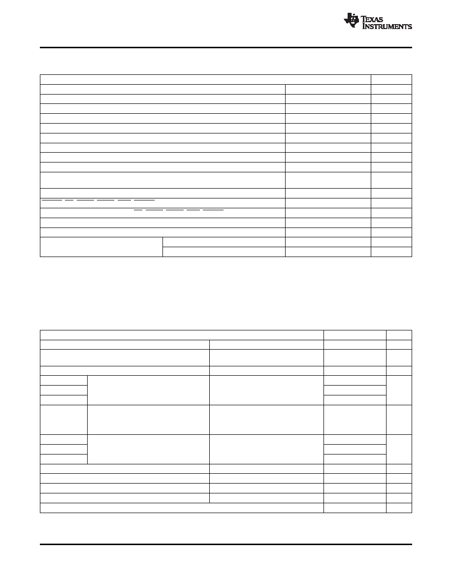
ABSOLUTE MAXIMUM RATINGS
over operating free-air temperature range unless otherwise noted
(1)
TAS5614A
UNIT
VDD to GND
–0.3 to 13.2
V
GVDD to GND
–0.3 to 13.2
V
PVDD_X to GND_X(2)
–0.3 to 53
V
OUT_X to GND_X(2)
–0.3 to 53
V
BST_X to GND_X(2)
–0.3 to 66.2
V
BST_X to GVDD_X(2)
–0.3 to 53
V
VREG to GND
–0.3 to 4.2
V
GND_X to GND
–0.3 to 0.3
V
GND to AGND
–0.3 to 0.3
V
OC_ADJ, M1, M2, M3, OSC_IO+, OSC_IO-, FREQ_ADJ, VI_CM, C_STARTUP, PSU_REF
–0.3 to 4.2
V
to GND
INPUT_X
–0.3 to 7
V
RESET, SD, OTW1, OTW2, CLIP, READY to GND
–0.3 to 7
V
Maximum continuous sink current (SD, OTW1, OTW2, CLIP, READY)
9
mA
Maximum operating junction temperature range, TJ
0 to 150
°C
Storage temperature, Tstg
–40 to 150
°C
Human body model(3) (all pins)
±2
kV
Electrostatic discharge
Charged device model(3) (all pins)
±500
V
(1)
Stresses beyond those listed under Absolute Maximum Ratings may cause permanent damage to the device. These are stress ratings
only, and functional operation of the device at these or any other conditions beyond those indicated under Recommended Operating
Conditions is not implied. Exposure to absolute-maximum-rated conditions for extended periods may affect device reliability.
(2)
These voltages represents the DC voltage + peak AC waveform measured at the terminal of the device in all conditions.
(3)
Failure to follow good anti-static ESD handling during manufacture and rework will contribute to device malfunction. Make sure the
operators handling the device are adequately grounded through the use of ground straps or alternative ESD protection.
RECOMMENDED OPERATING CONDITIONS
over operating free-air temperature range (unless otherwise noted)
MIN NOM
MAX
UNIT
PVDD_x
Half-bridge supply
DC supply voltage
18
36
38
V
Supply for logic regulators and gate-drive
GVDD_x
DC supply voltage
10.8
12
13.2
V
circuitry
VDD
Digital regulator supply voltage
DC supply voltage
10.8
12
13.2
V
RL(BTL)
3.5
4
Output filter according to schematics in
RL(SE)
Load impedance
2.8
3
the application information section.
RL(PBTL)
1.6
2
Output filter according to schematics in
the application information section. ROC =
RL(BTL)
Load impedance
2.8
3
Ω
22k
Ω, add Schottky diodes from OUT_X
to GND_X.
LOUTPUT(BTL)
7
10
LOUTPUT(SE)
Output filter inductance
Minimum output inductance at IOC
7
15
μH
LOUTPUT(PBTL)
7
10
FPWM
PWM frame rate
352
384
500
kHz
CPVDD
PVDD close decoupling capacitors
2
μF
ROC
Over-current programming resistor
Resistor tolerance = 5%
22
30
k
Ω
ROC_LATCHED
Over-current programming resistor
Resistor tolerance = 5%
47
64
k
Ω
TJ
Junction temperature
0
125
°C
4
Copyright
2010–2011, Texas Instruments Incorporated
Product Folder Link(s): TAS5614A
相關PDF資料 |
PDF描述 |
|---|---|
| TAS5614APHD | 150 W, 2 CHANNEL, AUDIO AMPLIFIER, PQFP64 |
| TAS5614PHD | 150 W, 2 CHANNEL, AUDIO AMPLIFIER, PQFP64 |
| TAS5614PHDR | 150 W, 2 CHANNEL, AUDIO AMPLIFIER, PQFP64 |
| TAS5615DKDR | 300 W, 2 CHANNEL, AUDIO AMPLIFIER, PDSO44 |
| TAS5615PHDR | 300 W, 2 CHANNEL, AUDIO AMPLIFIER, PQFP64 |
相關代理商/技術參數(shù) |
參數(shù)描述 |
|---|---|
| TAS5614DKD | 制造商:TI 制造商全稱:Texas Instruments 功能描述:150W STEREO / 300W MONO PurePath? HD DIGITAL-INPUT POWER STAGE |
| TAS5614L | 制造商:TI 制造商全稱:Texas Instruments 功能描述:TAS5612L-TAS5614LDDVEVM |
| TAS5614LA | 制造商:TI 制造商全稱:Texas Instruments 功能描述:150-W Stereo / 300-W Mono PurePath? HD Digital-Input Class-D Power Stage |
| TAS5614LADDV | 功能描述:音頻放大器 150W St/300W Mono HD Dig-In Pwr Stage RoHS:否 制造商:STMicroelectronics 產(chǎn)品:General Purpose Audio Amplifiers 輸出類型:Digital 輸出功率: THD + 噪聲: 工作電源電壓:3.3 V 電源電流: 最大功率耗散: 最大工作溫度: 安裝風格:SMD/SMT 封裝 / 箱體:TQFP-64 封裝:Reel |
| TAS5614LADDVEVM | 功能描述:音頻 IC 開發(fā)工具 TAS5614LA/TAS5612LA Eval Mod RoHS:否 制造商:Texas Instruments 產(chǎn)品:Evaluation Kits 類型:Audio Amplifiers 工具用于評估:TAS5614L 工作電源電壓:12 V to 38 V |
發(fā)布緊急采購,3分鐘左右您將得到回復。