- 您現(xiàn)在的位置:買賣IC網(wǎng) > PDF目錄372313 > ST92185 16K/24K/32K ROM HCMOS MCU WITH ON-SCREEN-DISPLAY PDF資料下載
參數(shù)資料
| 型號(hào): | ST92185 |
| 英文描述: | 16K/24K/32K ROM HCMOS MCU WITH ON-SCREEN-DISPLAY |
| 中文描述: | 16K/24K/32K光盤HCMOS微控制器屏幕顯示器 |
| 文件頁(yè)數(shù): | 146/230頁(yè) |
| 文件大?。?/td> | 2743K |
| 代理商: | ST92185 |
第1頁(yè)第2頁(yè)第3頁(yè)第4頁(yè)第5頁(yè)第6頁(yè)第7頁(yè)第8頁(yè)第9頁(yè)第10頁(yè)第11頁(yè)第12頁(yè)第13頁(yè)第14頁(yè)第15頁(yè)第16頁(yè)第17頁(yè)第18頁(yè)第19頁(yè)第20頁(yè)第21頁(yè)第22頁(yè)第23頁(yè)第24頁(yè)第25頁(yè)第26頁(yè)第27頁(yè)第28頁(yè)第29頁(yè)第30頁(yè)第31頁(yè)第32頁(yè)第33頁(yè)第34頁(yè)第35頁(yè)第36頁(yè)第37頁(yè)第38頁(yè)第39頁(yè)第40頁(yè)第41頁(yè)第42頁(yè)第43頁(yè)第44頁(yè)第45頁(yè)第46頁(yè)第47頁(yè)第48頁(yè)第49頁(yè)第50頁(yè)第51頁(yè)第52頁(yè)第53頁(yè)第54頁(yè)第55頁(yè)第56頁(yè)第57頁(yè)第58頁(yè)第59頁(yè)第60頁(yè)第61頁(yè)第62頁(yè)第63頁(yè)第64頁(yè)第65頁(yè)第66頁(yè)第67頁(yè)第68頁(yè)第69頁(yè)第70頁(yè)第71頁(yè)第72頁(yè)第73頁(yè)第74頁(yè)第75頁(yè)第76頁(yè)第77頁(yè)第78頁(yè)第79頁(yè)第80頁(yè)第81頁(yè)第82頁(yè)第83頁(yè)第84頁(yè)第85頁(yè)第86頁(yè)第87頁(yè)第88頁(yè)第89頁(yè)第90頁(yè)第91頁(yè)第92頁(yè)第93頁(yè)第94頁(yè)第95頁(yè)第96頁(yè)第97頁(yè)第98頁(yè)第99頁(yè)第100頁(yè)第101頁(yè)第102頁(yè)第103頁(yè)第104頁(yè)第105頁(yè)第106頁(yè)第107頁(yè)第108頁(yè)第109頁(yè)第110頁(yè)第111頁(yè)第112頁(yè)第113頁(yè)第114頁(yè)第115頁(yè)第116頁(yè)第117頁(yè)第118頁(yè)第119頁(yè)第120頁(yè)第121頁(yè)第122頁(yè)第123頁(yè)第124頁(yè)第125頁(yè)第126頁(yè)第127頁(yè)第128頁(yè)第129頁(yè)第130頁(yè)第131頁(yè)第132頁(yè)第133頁(yè)第134頁(yè)第135頁(yè)第136頁(yè)第137頁(yè)第138頁(yè)第139頁(yè)第140頁(yè)第141頁(yè)第142頁(yè)第143頁(yè)第144頁(yè)第145頁(yè)當(dāng)前第146頁(yè)第147頁(yè)第148頁(yè)第149頁(yè)第150頁(yè)第151頁(yè)第152頁(yè)第153頁(yè)第154頁(yè)第155頁(yè)第156頁(yè)第157頁(yè)第158頁(yè)第159頁(yè)第160頁(yè)第161頁(yè)第162頁(yè)第163頁(yè)第164頁(yè)第165頁(yè)第166頁(yè)第167頁(yè)第168頁(yè)第169頁(yè)第170頁(yè)第171頁(yè)第172頁(yè)第173頁(yè)第174頁(yè)第175頁(yè)第176頁(yè)第177頁(yè)第178頁(yè)第179頁(yè)第180頁(yè)第181頁(yè)第182頁(yè)第183頁(yè)第184頁(yè)第185頁(yè)第186頁(yè)第187頁(yè)第188頁(yè)第189頁(yè)第190頁(yè)第191頁(yè)第192頁(yè)第193頁(yè)第194頁(yè)第195頁(yè)第196頁(yè)第197頁(yè)第198頁(yè)第199頁(yè)第200頁(yè)第201頁(yè)第202頁(yè)第203頁(yè)第204頁(yè)第205頁(yè)第206頁(yè)第207頁(yè)第208頁(yè)第209頁(yè)第210頁(yè)第211頁(yè)第212頁(yè)第213頁(yè)第214頁(yè)第215頁(yè)第216頁(yè)第217頁(yè)第218頁(yè)第219頁(yè)第220頁(yè)第221頁(yè)第222頁(yè)第223頁(yè)第224頁(yè)第225頁(yè)第226頁(yè)第227頁(yè)第228頁(yè)第229頁(yè)第230頁(yè)
146/230
ST92163 - USB PERIPHERAL (USB)
USB INTERFACE (
Cont’d
)
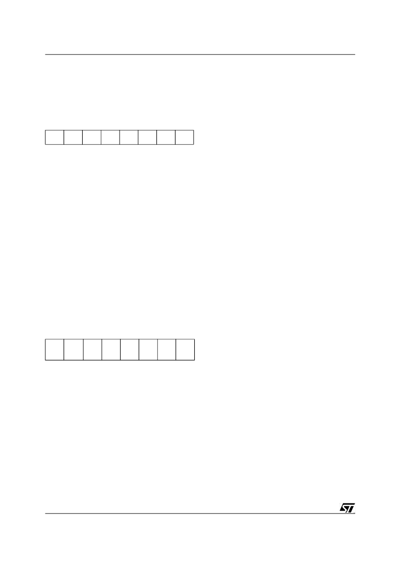
DEVICE n ADDRESS (DADDRn)
R240 to R247 - Read/Write
Register page: 15
Reset Value: 0000 0000 (00h)
Note:
This register is also reset when a USB reset
is received from the USB bus or forced through bit
FRES in the USBCTLR register.
Bit 7 =
EF
:
Enable Function
.
Set by software to enable the USB function whose
address is contained in the following ADD[6:0]
bits.
0: Function disabled
1: Function enabled
Bits 6:0 =
ADD[6:0]
:
Device Address
.
Software must write into these bits the USB device
address assigned by the host PC during the enu-
meration.
ENDPOINT n REGISTER A (EPnRA)
(TRANSMISSION)
R240-R254 (even)
Read/Write
Register pages: 4 & 5
Reset value: 0000 0000 (00h)
These registers are used for controlling data trans-
mission. They are also reset when a USB reset is
received or forced through the FRES bit in the US-
BCTLR register.
Note:
The CTR bits are not affected by a USB re-
set
Each endpoint has its EPnRA register where n is
the endpoint identifier in the range 0 to 15.
Bit 7 =
CTR
:
Correct Transfer
.
Set by hardware when a transaction is successful-
ly completed on this endpoint; software can only
clear this bit.
0: No correct transfer occurred
1: Correct transfer occurred
Note:
A transaction ended with a NAK or STALL
handshake does not set this bit, since no data is
actually transferred, as in the case of protocol er-
rors or data toggle mismatches. The CTR bit is
also used to perform flow control: while CTR=1, a
valid endpoint answers NAK to every transaction
addressed to it (except SETUP requests which are
simply ignored) until the application software ac-
knowledges the CTR event, resetting this bit. This
does not apply to isochronous endpoints where no
handshake phase is used.
Bit 6 =
DTOG_TX
:
Data Toggle, for transmission
transfers
.
If the endpoint is non-isochronous, this bit contains
the required value of the data toggle bit
(0=DATA0, 1=DATA1) for the next data packet to
be transmitted. Hardware toggles this bit when the
ACK handshake is received from the USB host,
following a data packet transmission. If the end-
point is defined as a control one, hardware sets
this bit to 1 on reception of a SETUP PID ad-
dressed to this endpoint.
If the endpoint is isochronous, this bit is used to
support DMA buffer swapping since no data tog-
gling is used for this sort of endpoint and only
DATA0 packet are transmitted. Hardware toggles
this bit just after the end of data packet transmis-
sion, since no handshake is used for isochronous
transfers.
Note:
this bit can be also written by software to in-
itialize it (mandatory when the endpoint is not a
control endpoint) or to force specific data toggle/
DMA buffer usage.
7
0
EF
ADD6
ADD5
ADD4
ADD3
ADD2
ADD1
ADD0
7
0
CTR
DTOG_
TX
STAT_
TX1
STAT_
TX0
PIDR1 PIDR0
CEP
ISO
相關(guān)PDF資料 |
PDF描述 |
|---|---|
| ST92186B | 8/16-BIT MCU FOR TV APPLICATIONS WITH UP TO 32K ROM AND ENHANCED ON-SCREEN-DISPLAY |
| ST92T163N4B1L | 8/16-BIT FULL SPEED USB MCU FOR COMPOSITE DEVICES WITH 16 ENDPOINTS. 20K ROM. 2K RAM. I 2 C. SCI. & MFT |
| ST92E195 | 48-96 KBYTE ROM HCMOS MCU WITH ON-SCREEN DISPLAY AND TELETEXT DATA SLICER |
| ST92F120JV1 | 8/16-BIT FLASH MCU FAMILY WITH RAM. EEPROM AND J1850 BLPD |
| ST92F120JV9 | 8/16-BIT FLASH MCU FAMILY WITH RAM. EEPROM AND J1850 BLPD |
相關(guān)代理商/技術(shù)參數(shù) |
參數(shù)描述 |
|---|---|
| ST92185B | 制造商:STMICROELECTRONICS 制造商全稱:STMicroelectronics 功能描述:16K/24K/32K ROM HCMOS MCU WITH ON-SCREEN-DISPLAY |
| ST92185B1 | 制造商:STMICROELECTRONICS 制造商全稱:STMicroelectronics 功能描述:16K/24K/32K ROM HCMOS MCU WITH ON-SCREEN-DISPLAY |
| ST92185B1BJ1 | 制造商:STMICROELECTRONICS 制造商全稱:STMicroelectronics 功能描述:16K/24K/32K ROM HCMOS MCU WITH ON-SCREEN-DISPLAY |
| ST92185B1BN1 | 制造商:STMICROELECTRONICS 制造商全稱:STMicroelectronics 功能描述:16K/24K/32K ROM HCMOS MCU WITH ON-SCREEN-DISPLAY |
| ST92185B1T1 | 制造商:STMICROELECTRONICS 制造商全稱:STMicroelectronics 功能描述:16K/24K/32K ROM HCMOS MCU WITH ON-SCREEN-DISPLAY |
發(fā)布緊急采購(gòu),3分鐘左右您將得到回復(fù)。