- 您現(xiàn)在的位置:買賣IC網(wǎng) > PDF目錄385870 > ST63E69D1 (意法半導體) 8-BIT HCMOS MCU FOR DIGITAL CONTROLLED MULTI FREQUENCYMONITOR PDF資料下載
參數(shù)資料
| 型號: | ST63E69D1 |
| 廠商: | 意法半導體 |
| 英文描述: | 8-BIT HCMOS MCU FOR DIGITAL CONTROLLED MULTI FREQUENCYMONITOR |
| 中文描述: | 8位HCMOS單片機的數(shù)控多FREQUENCYMONITOR |
| 文件頁數(shù): | 32/71頁 |
| 文件大小: | 584K |
| 代理商: | ST63E69D1 |
第1頁第2頁第3頁第4頁第5頁第6頁第7頁第8頁第9頁第10頁第11頁第12頁第13頁第14頁第15頁第16頁第17頁第18頁第19頁第20頁第21頁第22頁第23頁第24頁第25頁第26頁第27頁第28頁第29頁第30頁第31頁當前第32頁第33頁第34頁第35頁第36頁第37頁第38頁第39頁第40頁第41頁第42頁第43頁第44頁第45頁第46頁第47頁第48頁第49頁第50頁第51頁第52頁第53頁第54頁第55頁第56頁第57頁第58頁第59頁第60頁第61頁第62頁第63頁第64頁第65頁第66頁第67頁第68頁第69頁第70頁第71頁
PS2
PS1
PS0
Divided By
0
0
0
1
0
0
1
2
0
1
0
4
0
1
1
8
1
0
0
16
1
0
1
32
1
1
0
64
1
1
1
128
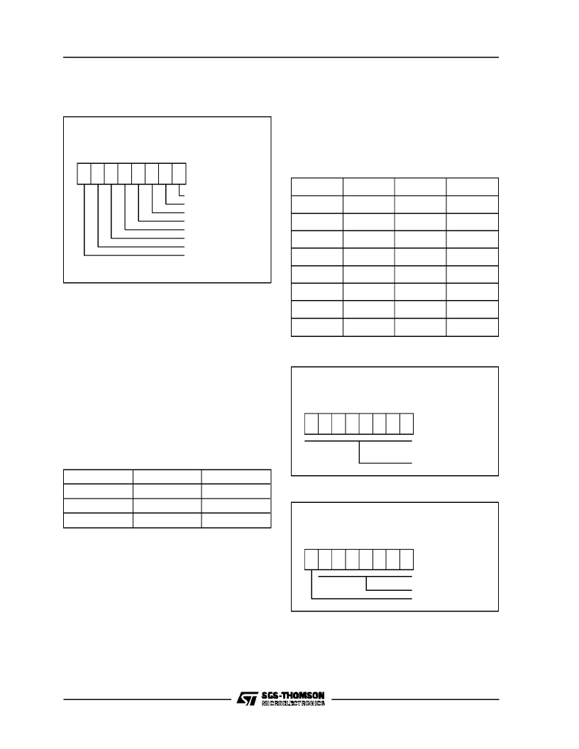
Table 9. Prescaler DivisionFactors
TSCR
Imer 1&2 Status ControlRegisters
DAH Timer 1, DCH Timer 2,
Read/ Write
D7 D6 D5 D4 D3 D2 D1 D0
PS0 =PrescalerMux. Select
PS1 =PrescalerMux. Select
PS2 =PrescalerMux. Select
PSI =PrescalerInitialize Bit
D4 = TimersEnable Bit
*
D5 = TimersEnable Bit
*
ETI = Enable TimerInterrupt
TMZ = TimerZero Bit
*
Only Available in TSCR1
Figure32. Timer Status Control Registers
TIMERS
(Continued)
TMZ.
Low-to-high transitionindicatesthatthetimer
count register has decrement to zero. This
must be cleared by user software before to start
with a newcount.
ETI.
This bit, when set, enablesthe timer interrupt
(vector#3forTimer1,vector#1forTimer2)request.
If ETI=0the timer interruptis disabled.IfETI=1 and
TMZ= 1an interruptrequestis generated.
D5.
This is the timers enable bit D5. It must be
cleared to0 togetherwith aset to 1 of bit D4 to en-
able both Timer 1 and Timer 2 functions. It is not
implemented on TSCR2 register.
D4.
This is the timers enable bit D4. This bit must
be setto 1 togetherwith aclear to 0 of bitD5 to en-
able both Timer 1 and Timer 2 functions. It is not
implemented on TSCR2 register.
bit
D5
D4
Timers
0
0
Disabled
0
1
Enabled
1
X
Reserved
PS1.
Used to initialize the prescaler and inhibit its
countingwhile PSI = 0 the prescaler is set to 7FH
andthe counteris inhibited.When PSI=1 the pres-
caler is enabled to count downwards. As long as
PSI=0 bothcounterand prescalerarenotrunning.
PS2-PS0.
Thesebits select thedivision ratioof the
prescaler register.(see table 9)
The TSCR1 and TSCR2 registers are cleared on
reset. The correct D4-D5 combination must be
written in TSCR1 by user’s software to enable the
operation of Timer 1 andTimer 2.
TCR
Timer Counter1&2 Register
D3H Timer 1,DBH Timer 2, Read/ Write
D7 D6 D5 D4 D3 D2 D1 D0
D7 -D0 =Counter bits
Figure 33. Timer CounterRegisters
PSC
TimerPrescaler 1&2 Register
D2H Timer 1,DAH Timer 2, Read/ Write
D7 D6 D5 D4 D3 D2 D1 D0
D6 -D0 =Prescalerbits
Always read as “0”
Figure 34. Timer CounterRegisters
ST6369
28/67
相關PDF資料 |
PDF描述 |
|---|---|
| ST700C12L0 | PHASE CONTROL THYRISTORS Hockey Puk Version |
| ST700C12L0L | PHASE CONTROL THYRISTORS Hockey Puk Version |
| ST700C12L1 | PHASE CONTROL THYRISTORS Hockey Puk Version |
| ST700C | PHASE CONTROL THYRISTORS Hockey Puk Version |
| ST700C12L2L | PHASE CONTROL THYRISTORS Hockey Puk Version |
相關代理商/技術參數(shù) |
參數(shù)描述 |
|---|---|
| ST63E73J5D1 | 制造商:STMICROELECTRONICS 制造商全稱:STMicroelectronics 功能描述:8-BIT ROM/OTP/EPROM MCUs FOR DIGITALLY CONTROLLED MULTISYNC/MULTISTANDARD MONITORS |
| ST63E85D1 | 制造商:STMICROELECTRONICS 制造商全稱:STMicroelectronics 功能描述:8-BIT MCUs WITH ON-SCREEN-DISPLAY FOR TV TUNING |
| ST63E85D1/XX | 制造商:未知廠家 制造商全稱:未知廠家 功能描述:8-Bit Microcontroller |
| ST63E87D1 | 制造商:STMICROELECTRONICS 制造商全稱:STMicroelectronics 功能描述:8-BIT MCUs WITH ON-SCREEN-DISPLAY FOR TV TUNING |
| ST63E87D1/XX | 制造商:未知廠家 制造商全稱:未知廠家 功能描述:8-Bit Microcontroller |
發(fā)布緊急采購,3分鐘左右您將得到回復。