- 您現(xiàn)在的位置:買賣IC網(wǎng) > PDF目錄299919 > SPX1004S1-L-1-2/TR 1-OUTPUT TWO TERM VOLTAGE REFERENCE, 1.235 V, PDSO8 PDF資料下載
參數(shù)資料
| 型號: | SPX1004S1-L-1-2/TR |
| 元件分類: | 基準(zhǔn)電壓源/電流源 |
| 英文描述: | 1-OUTPUT TWO TERM VOLTAGE REFERENCE, 1.235 V, PDSO8 |
| 封裝: | ROHS COMPLIANT, MS-012AA, SOIC-8 |
| 文件頁數(shù): | 2/9頁 |
| 文件大小: | 788K |
| 代理商: | SPX1004S1-L-1-2/TR |
2
Date: 05/17/07
SPX1004 1.2V/2.5V Micropower Voltage Reference
Copyright 2007 Sipex Corporation
Electrical characteristics are guaranteed over full junction temperature range (0
°C to 70°C). Ambient temperature must be
derated based on power dissipation and package thermal characteristics.
SPX1004-1.2V
SPX1004-2.5V
PARAMETER
CONDITIONS
MIN
TYP
MAX
MIN
TYP
MAX
UNITS
Reverse breakdown
I
Z=100A, TJ=25°C
1.225 1.235 1.245
2.480 2.500 2.520
V
0°C≤T
A≤70°C
1.219 1.235 1.251
2.470 2.500 2.530
Ave Temp. Coeff.
I
min≤IZ≤20mA
20
60
ppm/
°C
Min Operating Current
4
10
12
20
A
Reverse Breakdown
I
min≤IZ≤1mA
0.5
1
0.5
1
mV
Voltage Change
over temperature
0.5
1.5
0.5
1.5
with Current
1mA≤I
Z≤20mA
6.5
10
6.5
10
over temperature
6.5
20
6.5
20
Reverse Dynamic
I
Z=100A, f=25Hz
0.2
0.6
0.8
0.9
Impedance
over temperature
1
1.5
Wide Band Noise
I
Z=100A, 10Hz≤f≤10kHz
60
120
V
Long Term Stability
I
Z=100A, TA=25°C±0.1°C
20
60
ppm/
kHr
Operating Temp Range
0
70
0
70
°C
ABSOLUTE MAXIMUM RATINGS
Stresses greater than those listed under ABSOLUTE MAXIMUM
RATINGS may cause permanent damage to the device. This is a
stress rating only and functional operation of the device at these or
any other conditions above those indicated in the operational sections
of this specification is not implied. Exposure to absolute maximum
rating conditions for extended periods may affect reliability.
Forward Current (I
AK).....................................................10mA
Reverse Current (I
KA).....................................................30mA
Lead Temperature (soldering, 10 seconds).................300°C
Storage Temperature Range.......................-65°C to +150°C
Junction Temperature..................................................150°C
Continuous Power Dissipation (P
D)
TO-92.........................................................775mW
NSOIC-8.....................................................750mW
SOT-89.....................................................1000mW
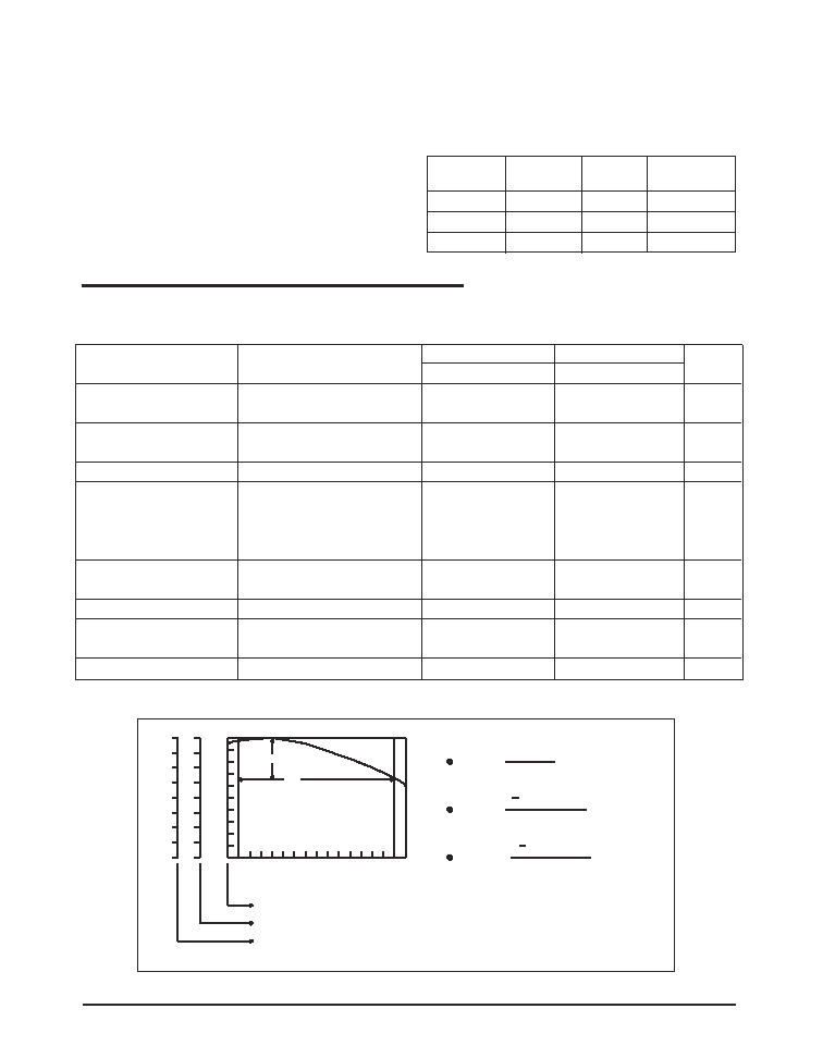
VK
0
15
30
45
60
75
90
105
-10
0.5
5000
0
0.07 mV/C
0.003 %/C
27 ppm/C
TC in mV/C =
TC in % /C =
VKA (mV)
T
A
T
A
VKA at 25C
VKA
x 100
(
)
TC in ppm/C =
T
A
VKA at 25C
VKA
x 106
(
)
ppm
%
mV
Junction Temperature (C)
Figure 2. V
REF vs Temperature for 2.5V Version
TYPICAL THERMAL RESISTANCES
PACKAGE
-0
JA
TYPICAL
DERATING
TO-92
160°C/W
80°C/W
6.3 mW/°C
NSOIC-8
175°C/W
45°C/W
5.7mW/°C
SOT-89
110°C/W
8°C/W
9.1mW/°C
ELECTRICAL CHARACTERISTICS
0
JA
-
相關(guān)PDF資料 |
PDF描述 |
|---|---|
| SPX1431N/TR | 1-OUTPUT TWO TERM VOLTAGE REFERENCE, 2.49 V, PBCY3 |
| SPX2810AM3-2.5/TR | 2.5 V FIXED POSITIVE LDO REGULATOR, 1.2 V DROPOUT, PDSO4 |
| SPX2810AM3-3.0/TR | 3 V FIXED POSITIVE LDO REGULATOR, 1.2 V DROPOUT, PDSO4 |
| SPX2810AR-2.5/TR | 2.5 V FIXED POSITIVE LDO REGULATOR, 1.2 V DROPOUT, PSSO2 |
| SPX2810AR-3.0/TR | 3 V FIXED POSITIVE LDO REGULATOR, 1.2 V DROPOUT, PSSO2 |
相關(guān)代理商/技術(shù)參數(shù) |
參數(shù)描述 |
|---|---|
| SPX1004S1-L-2-5 | 制造商:SIPEX 制造商全稱:Sipex Corporation 功能描述:1.2V / 2.5V Micropower Voltage Reference |
| SPX1004S1-L-2-5/TR | 制造商:SIPEX 制造商全稱:Sipex Corporation 功能描述:1.2V / 2.5V Micropower Voltage Reference |
| SPX1004S2-1.2 | 制造商:SIPEX 制造商全稱:Sipex Corporation 功能描述:1.2V / 2.5V Micropower Voltage Reference |
| SPX1004S2-1.2/TR | 制造商:SIPEX 制造商全稱:Sipex Corporation 功能描述:1.2V / 2.5V Micropower Voltage Reference |
| SPX1004S2-1-2 | 制造商:SIPEX 制造商全稱:Sipex Corporation 功能描述:1.2V / 2.5V Micropower Voltage Reference |
發(fā)布緊急采購,3分鐘左右您將得到回復(fù)。