- 您現(xiàn)在的位置:買(mǎi)賣(mài)IC網(wǎng) > PDF目錄98100 > SNJ54AS646JT (TEXAS INSTRUMENTS INC) AS SERIES, 8-BIT REGISTERED TRANSCEIVER, TRUE OUTPUT, CDIP24 PDF資料下載
參數(shù)資料
| 型號(hào): | SNJ54AS646JT |
| 廠商: | TEXAS INSTRUMENTS INC |
| 元件分類(lèi): | 總線收發(fā)器 |
| 英文描述: | AS SERIES, 8-BIT REGISTERED TRANSCEIVER, TRUE OUTPUT, CDIP24 |
| 封裝: | 0.300 INCH, CERAMIC, DIP-24 |
| 文件頁(yè)數(shù): | 7/28頁(yè) |
| 文件大?。?/td> | 658K |
| 代理商: | SNJ54AS646JT |
第1頁(yè)第2頁(yè)第3頁(yè)第4頁(yè)第5頁(yè)第6頁(yè)當(dāng)前第7頁(yè)第8頁(yè)第9頁(yè)第10頁(yè)第11頁(yè)第12頁(yè)第13頁(yè)第14頁(yè)第15頁(yè)第16頁(yè)第17頁(yè)第18頁(yè)第19頁(yè)第20頁(yè)第21頁(yè)第22頁(yè)第23頁(yè)第24頁(yè)第25頁(yè)第26頁(yè)第27頁(yè)第28頁(yè)
SN54ALS646, SN54ALS648, SN54AS646
SN74ALS646A, SN74ALS648A, SN74AS646, SN74AS648
OCTAL BUS TRANSCEIVERS AND REGISTERS WITH 3-STATE OUTPUTS
SDAS039F – DECEMBER 1983 – REVISED JANUARY 1995
15
POST OFFICE BOX 655303
DALLAS, TEXAS 75265
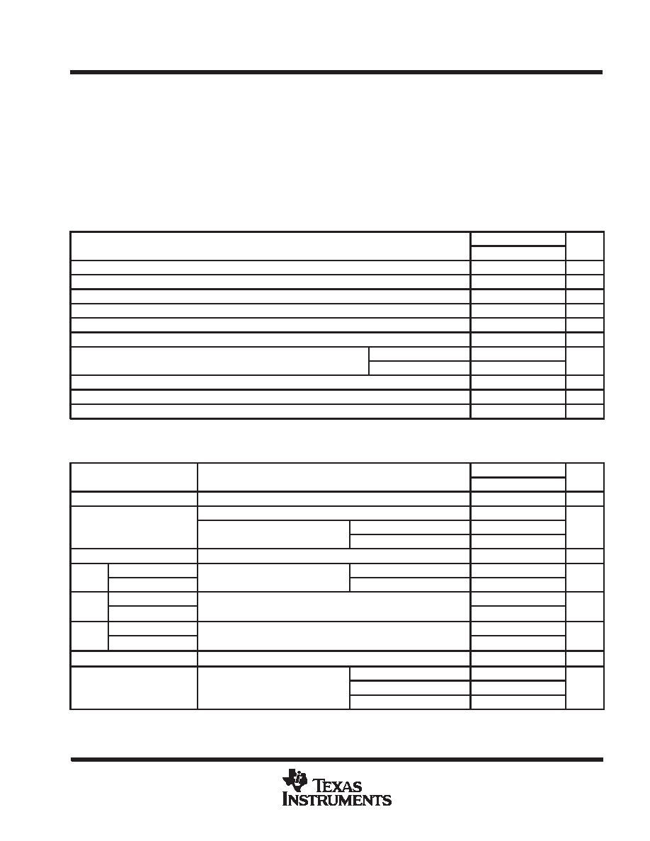
absolute maximum ratings over operating free-air temperature range (unless otherwise noted)
Supply voltage, VCC
7 V
. . . . . . . . . . . . . . . . . . . . . . . . . . . . . . . . . . . . . . . . . . . . . . . . . . . . . . . . . . . . . . . . . . . . . . .
Input voltage, VI: Control inputs
7 V
. . . . . . . . . . . . . . . . . . . . . . . . . . . . . . . . . . . . . . . . . . . . . . . . . . . . . . . . . . . . . .
I / O ports
5.5 V
. . . . . . . . . . . . . . . . . . . . . . . . . . . . . . . . . . . . . . . . . . . . . . . . . . . . . . . . . . . . . . . .
Operating free-air temperature range, TA: SN74AS648
0
°C to 70°C
. . . . . . . . . . . . . . . . . . . . . . . . . . . . . . . . .
Storage temperature range
– 65
°C to 150°C
. . . . . . . . . . . . . . . . . . . . . . . . . . . . . . . . . . . . . . . . . . . . . . . . . . . . . . .
Stresses beyond those listed under “absolute maximum ratings” may cause permanent damage to the device. These are stress ratings only, and
functional operation of the device at these or any other conditions beyond those indicated under “recommended operating conditions” is not
implied. Exposure to absolute-maximum-rated conditions for extended periods may affect device reliability.
recommended operating conditions
SN74AS648
UNIT
MIN
NOM
MAX
UNIT
VCC
Supply voltage
4.5
5
5.5
V
VIH
High-level input voltage
2
V
VIL
Low-level input voltage
0.8
V
IOH
High-level output current
–15
mA
IOL
Low-level output current
48
mA
fclock
Clock frequency
0
90
MHz
t
Pulse duration
CLKBA or CLKAB high
5
ns
tw
Pulse duration
CLKBA or CLKAB low
6
ns
tsu
Setup time, A before CLKAB
↑ or B before CLKBA↑
6
ns
th
Hold time, A after CLKAB
↑ or B before CLKBA
0
ns
TA
Operating free-air temperature
0
70
°C
electrical characteristics over recommended operating free-air temperature range (unless
otherwise noted)
PARAMETER
TEST CONDITIONS
SN74AS648
UNIT
PARAMETER
TEST CONDITIONS
MIN
TYP
MAX
UNIT
VIK
VCC = 4.5 V,
II = – 18 mA
– 1.2
V
VCC = 4.5 V to 5.5 V,
IOH = – 2 mA
VCC –2
VOH
VCC =4 5V
IOH = – 3 mA
2.4
3.2
V
VCC = 4.5 V
IOH = – 15 mA
2
VOL
VCC = 4.5 V,
IOL = 48 mA
0.35
0.5
V
II
Control inputs
VCC =5 5V
VI = 7 V
0.1
mA
II
A or B ports
VCC = 5.5 V
VI = 5.5 V
0.1
mA
I
Control inputs
V5 5 V
V2 7 V
20
A
IIH
A or B ports§
VCC = 5.5 V,
VI = 2.7 V
70
A
I
Control input
V5 5 V
V0 4 V
– 0.5
mA
IIL
A or B ports§
VCC = 5.5 V,
VI = 0.4 V
– 0.75
mA
IO
VCC = 5.5 V,
VO = 2.25 V
–30
–112
mA
Outputs high
110
185
ICC
VCC = 5.5 V
Outputs low
120
195
mA
Outputs disabled
120
195
All typical values are at VCC = 5 V, TA = 25 °C.
§ For I/O ports, the parameters IIH and IIL include the off-state output current.
The output conditions have been chosen to produce a current that closely approximates one half of the true short-circuit output current, IOS.
相關(guān)PDF資料 |
PDF描述 |
|---|---|
| SNJ54ALS648FK | ALS SERIES, 8-BIT REGISTERED TRANSCEIVER, INVERTED OUTPUT, CQCC28 |
| SNJ54AS646FK | AS SERIES, 8-BIT REGISTERED TRANSCEIVER, TRUE OUTPUT, CQCC28 |
| SN74ALS646A-1DW | ALS SERIES, 8-BIT REGISTERED TRANSCEIVER, TRUE OUTPUT, PDSO24 |
| SN74ALS648ADWRE4 | ALS SERIES, 8-BIT REGISTERED TRANSCEIVER, INVERTED OUTPUT, PDSO24 |
| SN74ALS651ADWRE4 | ALS SERIES, 8-BIT REGISTERED TRANSCEIVER, INVERTED OUTPUT, PDSO24 |
相關(guān)代理商/技術(shù)參數(shù) |
參數(shù)描述 |
|---|---|
| SNJ54AS652JT | 制造商:Texas Instruments 功能描述: |
| SNJ54AS652W | 制造商:Rochester Electronics LLC 功能描述:- Bulk |
| SNJ54AS74AJ | 制造商:Rochester Electronics LLC 功能描述:- Bulk 制造商:Texas Instruments 功能描述: 制造商:Texas Instruments 功能描述:Flip Flop D-Type Pos-Edge 2-Element 14-Pin CDIP Tube |
| SNJ54AS74J | 制造商:Rochester Electronics LLC 功能描述:- Bulk |
| SNJ54AS74W | 制造商:undefined 功能描述: |
發(fā)布緊急采購(gòu),3分鐘左右您將得到回復(fù)。