- 您現(xiàn)在的位置:買賣IC網(wǎng) > PDF目錄192857 > SDC-14587-444 (DATA DEVICE CORP) SYNCHRO OR RESOLVER TO DIGITAL CONVERTER, DIP36 PDF資料下載
參數(shù)資料
| 型號(hào): | SDC-14587-444 |
| 廠商: | DATA DEVICE CORP |
| 元件分類: | 位置變換器 |
| 英文描述: | SYNCHRO OR RESOLVER TO DIGITAL CONVERTER, DIP36 |
| 封裝: | DDIP-36 |
| 文件頁數(shù): | 12/18頁 |
| 文件大小: | 202K |
| 代理商: | SDC-14587-444 |
3
Data Device Corporation
www.ddc-web.com
SDC-14580
H-05/04-0
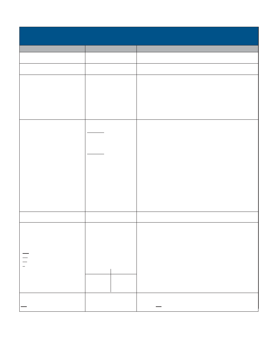
TABLE 1. SDC-14580 SPECIFICATIONS
These specifications apply over temperature range, power supply range, reference frequency, and amplitude range
+10% signal amplitude variation and up to 10% harmonic distortion in the reference.
PARAMETER
VALUE
COMMENT
RESOLUTION
ACCURACY GRADES
10, 12, 14, or 16 bits
±4, ±2, or ±1 minutes
DIFFERENTIAL LINEARITY
REPEATABILITY
1 LSB max in the 16th bit
1 LSB max
REF INPUT CHARACTERISTICS
Voltage Range
Carrier Frequency Ranges
10, 12, or 14 bit
16 bit
Input Impedance
Single Ended Input
Differential
Common Mode Range
1-35 Vrms
1-5 kHz (full accuracy)
2-5 kHz
50 kOhm min
100 kOhm min
50 V peak max
200 V transient peak
Up to 10 kHz with reduced accuracy.
SIGNAL INPUT CHARACTERISTICS
Synchro
Zin Line to Line
Zin Each line to ground
Common Mode Range
Resolver
Zin Single Ended
Zin Differential
Zin Each line to ground
Common Mode Range
Direct (2.0 V L-L)
Input Signal Type
sin/cos Range
Max Voltage Without Damage
Input lmpedance
11.8 V L-L
17.5 kOhm
11.5 kOhm
60 V max
11.8 V L-L
23 kOhm
46 kOhm
23 kOhm
60 V max
2 Vrms nom, 2.2 Vrms max
15 V CONTINUOUS,
100 V PEAK TRANSIENT
Zin > 20M//10 pF
Voltage options and minimum input impedance balanced.
Sin and cos resolver signals referenced to converter internal DC reference
voltage, V.
REFERENCE SYNTHESIZER
±Sig/Ref Phase Shift
60° typ, 45° min
DIGITAL INPUTS
Logic Type
Inputs
Max Input Voltage w/o Damage
Loading
INH (Inhibit)
EN (Enable bits 1-8) and
EL (Enable bits 9-16)
S (Control Transformer)
Resolution Control
10 Bit
12 Bit
14 Bit
16 Bit
Logic 0 = 0.8 V max
Logic 1 = 2.0 V min
-0.3 Vdc to +8 Vdc
10 A max
B (pin 36)
A (pin 35)
0
1
0
1
TTL/CMOS compatible.
Pull-up current source to +5 V//5 pF max, CMOS transient protected.
Logic 0 inhibits, Logic 1 enables, Data stable within 0.3 s.
Logic 0 enables, Logic 1 high Z within 100 ns, Data valid within 150 ns.
Logic 0 for Control Transformer, Logic 1 for normal tracking.
Unused output bits are at logic 0.
DIGITAL OUTPUTS
Parallel Data
CB (Converter Busy)
BIT (Built-ln-Test)
10, 12, 14, or 16 bits
0.4 s to 1.0 s
Natural binary angle positive logic.
Positive pulse; leading edge indicates counter update.
Logic 0 for BIT condition.
Pin Programmable.
Max +1 LSB of selected resolution, see TABLE 8 and Ordering Information.
發(fā)布緊急采購,3分鐘左右您將得到回復(fù)。