- 您現(xiàn)在的位置:買(mǎi)賣(mài)IC網(wǎng) > PDF目錄374727 > SC412AMLTRT (Semtech Corporation) Synchronous Buck Controller PDF資料下載
參數(shù)資料
| 型號(hào): | SC412AMLTRT |
| 廠商: | Semtech Corporation |
| 英文描述: | Synchronous Buck Controller |
| 中文描述: | 同步降壓控制器 |
| 文件頁(yè)數(shù): | 9/22頁(yè) |
| 文件大小: | 639K |
| 代理商: | SC412AMLTRT |
第1頁(yè)第2頁(yè)第3頁(yè)第4頁(yè)第5頁(yè)第6頁(yè)第7頁(yè)第8頁(yè)當(dāng)前第9頁(yè)第10頁(yè)第11頁(yè)第12頁(yè)第13頁(yè)第14頁(yè)第15頁(yè)第16頁(yè)第17頁(yè)第18頁(yè)第19頁(yè)第20頁(yè)第21頁(yè)第22頁(yè)
9
2006 Semtech Corp.
www.semtech.com
SC412A
POWER MANAGEMENT
Applications Information
(continued)
Enable Input
The EN is used to disable or enable the SC412A. When
EN is low (grounded), the SC412A is off and in its lowest-
power state. When EN is high the controller is enabled and
switching will begin
.
PSAVE Operation
The SC412A provides automatic power save operation at
light loads. The internal Zero-Cross comparator looks for
inductor current (via the voltage across the lower MOSFET)
to fall to zero on 8 consecutive cycles. Once observed, the
controller then enters power save and turns off the low-side
MOSFET on each cycle when the current crosses zero. To
add hysteresis, the on-time is increased by 25% in power-
save. The ef
fi
ciency improvement at light loads more than
offsets the disadvantage of slightly higher output ripple. If
the inductor current does not cross zero on any switching
cycle, the controller immediately exits power save. Since
the controller counts zero crossings, the converter can
sink current as long as the current does not cross zero on
eight consecutive cycles. This allows the output voltage to
recover quickly in response to negative load steps.
Smart Power Save Protection
In some applications, active loads can leak current from a
higher voltage and thereby cause VOUT to slowly rise and
reach the OVP threshold, leading to a hard shutdown. The
SC412A uses Smart Power Save to prevent this. When the
feedback signal exceeds 8% above nominal (810mV), the IC
exits power save operation (if already active) and DL drives
high to turn on the low-side MOSFET, which draws current
from VOUT via the inductor. When FB drops back to the
0.75V trip point, a normal TON switching cycle begins. This
method cycles energy from VOUT back to VBAT and prevents
a hard OVP shutdown, and also minimizes operating power
by avoiding continuous conduction-mode operation.
Current Limit Circuit
Current limiting can be accomplished in two ways. The RD-
SON of the lower MOSFET can be used as a current sensing
element, or a sense resistor at the lower MOSFET source
can be used if greater accuracy is needed. RDSON sensing
is more ef
fi
cient and less expensive. In both cases, the R
ILIM
resistor sets the over-current threshold. The R
ILIM
connects
from the ILIM pin to either the lower MOSFET drain (for RD-
SON sensing) or the high side of the current-sense resistor.
R
ILIM
connects to a 10
μ
A current source from the ILIM pin
which turns on when the low-side MOSFET turns on, after
the on-time DH pulse has completed. If the voltage drop
across the sense resistor or low-side MOSFET exceeds the
voltage across the R
ILIM
resistor, current limit will activate.
The high-side MOSFET will then not turn on until the voltage
drop across the sense element (resistor or MOSFET) falls
below the voltage across the R
ILIM
resistor.
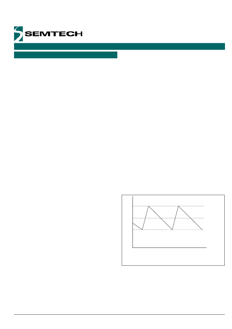
This current sensing scheme actually regulates the inductor
valley current, see Figure 3. This means that if the current
limit is set to 10A, the peak current through the inductor
would be 10A plus the peak ripple current, and the average
current through the inductor would be 10A plus 1/2 the
peak-to-peak ripple current.
I
LIMIT
I
LOAD
I
PEAK
I
TIME
Valley Current Limit
Figure 3.
相關(guān)PDF資料 |
PDF描述 |
|---|---|
| SC4150 | Negative Voltage Hot Swap Controller |
| SC4150HIS-4TRT | Negative Voltage Hot Swap Controller |
| SC4150HISTRT | Negative Voltage Hot Swap Controller |
| SC4150LIS-4TRT | Negative Voltage Hot Swap Controller |
| SC4150LISTRT | Negative Voltage Hot Swap Controller |
相關(guān)代理商/技術(shù)參數(shù) |
參數(shù)描述 |
|---|---|
| SC41342 | 制造商:MOTOROLA 制造商全稱:Motorola, Inc 功能描述:Encoder and Decoder Pairs CMOS |
| SC41342D | 制造商:MOTOROLA 制造商全稱:Motorola, Inc 功能描述:Encoder and Decoder Pairs CMOS |
| SC41342P | 制造商:MOTOROLA 制造商全稱:Motorola, Inc 功能描述:Encoder and Decoder Pairs CMOS |
| SC41343 | 制造商:MOTOROLA 制造商全稱:Motorola, Inc 功能描述:Encoder and Decoder Pairs CMOS |
| SC41343D | 制造商:MOTOROLA 制造商全稱:Motorola, Inc 功能描述:Encoder and Decoder Pairs CMOS |
發(fā)布緊急采購(gòu),3分鐘左右您將得到回復(fù)。