- 您現在的位置:買賣IC網 > PDF目錄372115 > SAA7372 (NXP SEMICONDUCTORS) Digital servo processor and Compact Disc decoder CD7 PDF資料下載
參數資料
| 型號: | SAA7372 |
| 廠商: | NXP SEMICONDUCTORS |
| 元件分類: | 消費家電 |
| 英文描述: | Digital servo processor and Compact Disc decoder CD7 |
| 中文描述: | SPECIALTY CONSUMER CIRCUIT, PQFP64 |
| 封裝: | 14 X 14 MM, 2.70 MM HEIGHT, PLASTIC, MS-022, SOT-393-1, QFP-64 |
| 文件頁數: | 20/60頁 |
| 文件大?。?/td> | 323K |
| 代理商: | SAA7372 |
第1頁第2頁第3頁第4頁第5頁第6頁第7頁第8頁第9頁第10頁第11頁第12頁第13頁第14頁第15頁第16頁第17頁第18頁第19頁當前第20頁第21頁第22頁第23頁第24頁第25頁第26頁第27頁第28頁第29頁第30頁第31頁第32頁第33頁第34頁第35頁第36頁第37頁第38頁第39頁第40頁第41頁第42頁第43頁第44頁第45頁第46頁第47頁第48頁第49頁第50頁第51頁第52頁第53頁第54頁第55頁第56頁第57頁第58頁第59頁第60頁
1998 Feb 26
20
Philips Semiconductors
Product specification
Digital servo processor and Compact Disc
decoder (CD7)
SAA7372
7.12
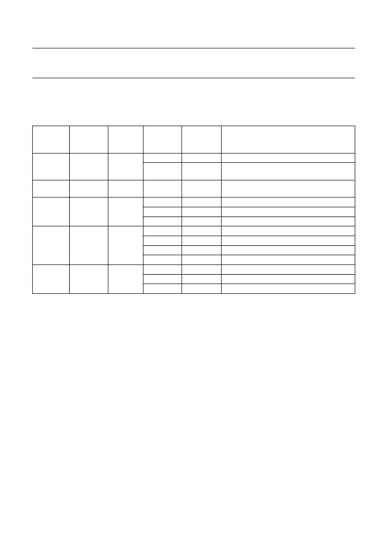
The VIA interface
The SAA7372 has five pins that can be reconfigured for different applications (see Table 8).
Table 8
Pin applications
PIN NAME
PIN
NUMBER
TYPE
CONTROL
REGISTER
ADDRESS
CONTROL
REGISTER
DATA
FUNCTION
V1
62
input
1100
xxx1
xxx0
external off-track signal input
internal off-track signal used, input may be read
via decoder status bit; selected via register 2
input may be read via decoder status bit;
selected via register 2
KILL output for right channel
output = 0
output = 1
4-line motor drive (using V4 and V5)
Q-to-W subcode output
output = 0
output = 1
de-emphasis output (active HIGH)
output = 0
output = 1
V2
63
input
V3
42
output
1100
1101
1101
xx0x
x01x
x11x
0000
xx01
xx10
xx11
01xx
10xx
11xx
V4
41
output
V5
40
output
7.13
Spindle motor control
7.13.1
M
OTOR OUTPUT MODES
The spindle motor speed is controlled by a fully integrated
digital servo. Address information from the internal
±
8 frame FIFO and disc speed information are used to
calculate the motor control output signals. Several output
modes, selected by register 6, are supported:
Pulse density, 2-line (true complement output),
(1
×
n) MHz sample frequency
PWM output, 2-line, (22.05
×
n) kHz modulation
frequency
PWM output, 4-line, (22.05
×
n) kHz modulation
frequency
CDV motor mode.
7.13.1.1
Pulse density output mode
In the pulse density mode the motor output pin (MOTO1)
is the pulse density modulated motor output signal. A 50%
duty factor corresponds with the motor not actuated,
higher duty factors mean acceleration, lower mean
braking. In this mode, the MOTO2 signal is the inverse of
the MOTO1 signal. Both signals change state only on the
edges of a (1
×
n) MHz internal clock signal. Possible
application diagrams are illustrated in Fig.13.
7.13.1.2
PWM output mode (2-line)
In the PWM mode the motor acceleration signal is put in
pulse-width modulation form on the MOTO1 output. The
motor braking signal is pulse-width modulated on the
MOTO2 output. The timing is illustrated in Fig.14. A typical
application diagram is illustrated in Fig.15.
相關PDF資料 |
PDF描述 |
|---|---|
| SAA7373 | Digital servo processor and Compact Disc decoder CD7 |
| SAA7373GP | Digital servo processor and Compact Disc decoder CD7 |
| SAA7374 | Low voltage digital servo processor and Compact Disc decoder CD7LV |
| SAA7374GP | Low voltage digital servo processor and Compact Disc decoder CD7LV |
| SAA7376 | Digital servo processor and Compact Disc decoder CD7 |
相關代理商/技術參數 |
參數描述 |
|---|---|
| SAA7373 | 制造商:PHILIPS 制造商全稱:NXP Semiconductors 功能描述:Digital servo processor and Compact Disc decoder CD7 |
| SAA7373GP | 制造商:PHILIPS 制造商全稱:NXP Semiconductors 功能描述:Digital servo processor and Compact Disc decoder CD7 |
| SAA7374 | 制造商:PHILIPS 制造商全稱:NXP Semiconductors 功能描述:Low voltage digital servo processor and Compact Disc decoder CD7LV |
| SAA7374GP | 制造商:PHILIPS 制造商全稱:NXP Semiconductors 功能描述:Low voltage digital servo processor and Compact Disc decoder CD7LV |
| SAA7376 | 制造商:PHILIPS 制造商全稱:NXP Semiconductors 功能描述:Digital servo processor and Compact Disc decoder CD7 |
發(fā)布緊急采購,3分鐘左右您將得到回復。