- 您現(xiàn)在的位置:買(mǎi)賣(mài)IC網(wǎng) > PDF目錄373273 > RH80532NC017256 Microprocessor PDF資料下載
參數(shù)資料
| 型號(hào): | RH80532NC017256 |
| 元件分類(lèi): | 微處理器 |
| 英文描述: | Microprocessor |
| 中文描述: | 微處理器 |
| 文件頁(yè)數(shù): | 37/93頁(yè) |
| 文件大小: | 2353K |
| 代理商: | RH80532NC017256 |
第1頁(yè)第2頁(yè)第3頁(yè)第4頁(yè)第5頁(yè)第6頁(yè)第7頁(yè)第8頁(yè)第9頁(yè)第10頁(yè)第11頁(yè)第12頁(yè)第13頁(yè)第14頁(yè)第15頁(yè)第16頁(yè)第17頁(yè)第18頁(yè)第19頁(yè)第20頁(yè)第21頁(yè)第22頁(yè)第23頁(yè)第24頁(yè)第25頁(yè)第26頁(yè)第27頁(yè)第28頁(yè)第29頁(yè)第30頁(yè)第31頁(yè)第32頁(yè)第33頁(yè)第34頁(yè)第35頁(yè)第36頁(yè)當(dāng)前第37頁(yè)第38頁(yè)第39頁(yè)第40頁(yè)第41頁(yè)第42頁(yè)第43頁(yè)第44頁(yè)第45頁(yè)第46頁(yè)第47頁(yè)第48頁(yè)第49頁(yè)第50頁(yè)第51頁(yè)第52頁(yè)第53頁(yè)第54頁(yè)第55頁(yè)第56頁(yè)第57頁(yè)第58頁(yè)第59頁(yè)第60頁(yè)第61頁(yè)第62頁(yè)第63頁(yè)第64頁(yè)第65頁(yè)第66頁(yè)第67頁(yè)第68頁(yè)第69頁(yè)第70頁(yè)第71頁(yè)第72頁(yè)第73頁(yè)第74頁(yè)第75頁(yè)第76頁(yè)第77頁(yè)第78頁(yè)第79頁(yè)第80頁(yè)第81頁(yè)第82頁(yè)第83頁(yè)第84頁(yè)第85頁(yè)第86頁(yè)第87頁(yè)第88頁(yè)第89頁(yè)第90頁(yè)第91頁(yè)第92頁(yè)第93頁(yè)
Mobile Intel
Pentium
4 Processor-M
250686-002
Datasheet
37
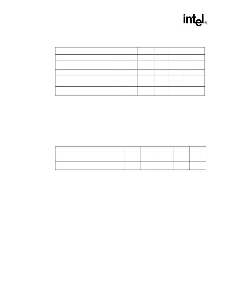
NOTES:
1. Unless otherwise noted, all specifications in this table apply to all processor frequencies.
2. All AC timings for the Asynch GTL+ signals are referenced to the BCLK0 rising edge at Crossing Voltage. All
Asynch GTL+ signal timings are referenced at GTLREF. PWRGOOD is referenced o the BCLK0 rising edge
at 0.5*VCC.
3. These signals may be driven asynchronously.
4. Refer to the PWRGOOD definition for more details regarding the behavior of this signal.
5. Length of assertion for PROCHOT# does not equal internal clock modulation time. Time is allocated after the
assertion and before the deassertion of PROCHOT# for the processor to complete current instruction
execution.
6. See
Section 7.1
for additional timing requirements for entering and leaving the low power states.
NOTES:
1. Before the deassertion of RESET#.
2. After clock that deasserts RESET#.
Table 21. Miscellaneous Signals AC Specifications
T# Parameter
Min
Max
Unit
Figure
Notes
1,2,3,6
T35: Asynch GTL+ Input Pulse Width
2
BCLKs
T36: PWRGOOD to RESET# Deassertion
Time
1
10
ms
16
T37: PWRGOOD Inactive Pulse Width
10
BCLKs
16
4
T38: PROCHOT# Pulse Width
500
μ
s
18
5
T39: THERMTRIP# to Vcc Removal
0.5
s
19
T40: FERR# Valid Delay from STPCLK#
Deassertion
0
5
BCLKs
20
Table 22. System Bus AC Specifications (Reset Conditions)
T# Parameter
Min
Max
Unit
Figure
Notes
T45: Reset Configuration Signals (A[31:3]#,
BR0#, INIT#, SMI#) Setup Time
4
BCLKs
13
1
T46: Reset Configuration Signals (A[31:3]#,
BR0#, INIT#, SMI#) Hold Time
2
20
BCLKs
13
2
相關(guān)PDF資料 |
PDF描述 |
|---|---|
| RH80532NC021256 | Microprocessor |
| RH80532NC025256 | Microprocessor |
| RH80532NC029256 | Microprocessor |
| RH80532NC033256 | Microprocessor |
| RHE070 | Poly Switch PTC DEVICES |
相關(guān)代理商/技術(shù)參數(shù) |
參數(shù)描述 |
|---|---|
| RH80532NC021256 | 制造商:未知廠家 制造商全稱(chēng):未知廠家 功能描述:Microprocessor |
| RH80532NC025256 | 制造商:未知廠家 制造商全稱(chēng):未知廠家 功能描述:Microprocessor |
| RH80532NC029256 | 制造商:未知廠家 制造商全稱(chēng):未知廠家 功能描述:Microprocessor |
| RH80532NC033256 | 制造商:未知廠家 制造商全稱(chēng):未知廠家 功能描述:Microprocessor |
| RH80532NC049256 | 制造商:Rochester Electronics LLC 功能描述:- Bulk |
發(fā)布緊急采購(gòu),3分鐘左右您將得到回復(fù)。