- 您現(xiàn)在的位置:買賣IC網(wǎng) > PDF目錄297235 > RD-19230FX-202T (DATA DEVICE CORP) SYNCHRO OR RESOLVER TO DIGITAL CONVERTER, PQFP64 PDF資料下載
參數(shù)資料
| 型號(hào): | RD-19230FX-202T |
| 廠商: | DATA DEVICE CORP |
| 元件分類: | 位置變換器 |
| 英文描述: | SYNCHRO OR RESOLVER TO DIGITAL CONVERTER, PQFP64 |
| 封裝: | 0.520 X 0.520 INCH, PLASTIC, QFP-64 |
| 文件頁數(shù): | 22/23頁 |
| 文件大?。?/td> | 476K |
| 代理商: | RD-19230FX-202T |
8
Data Device Corporation
www.ddc-web.com
RD-19230
W-05/08-0
*
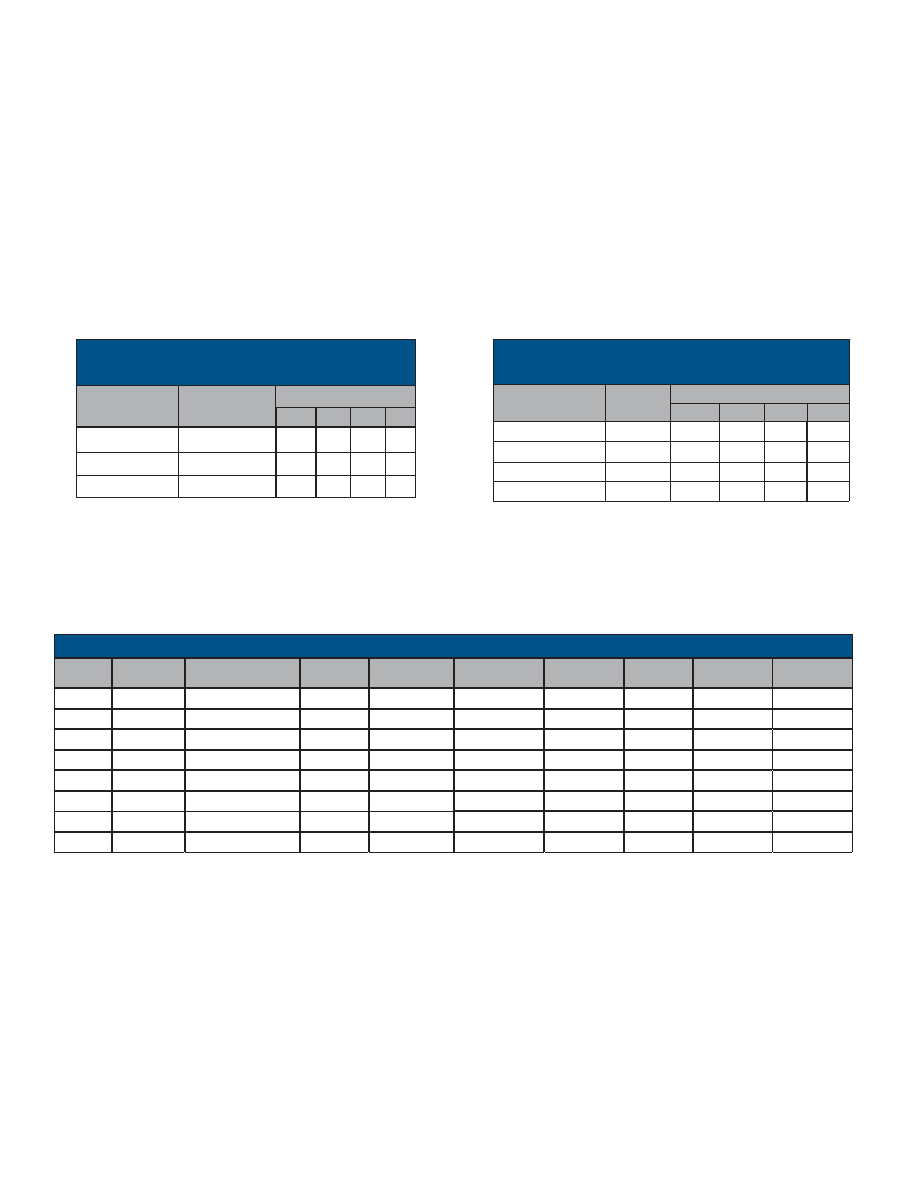
10
*
10
15k
20k
23k
7
10
30k
23k
5
7
10
30k
30k** or open
16
14
12
10
RESOLUTION
RS/ RCLK
(
Ω
Ω)
RC / RSET
(
Ω
Ω)
TABLE 4. CARRIER FREQUENCY (MAX) IN KHZ
* Not recommended.
** The use of a high quality thin-film resistor will provide better temperature
stability than leaving open.
Note: RC “Rcurrent” = RSET
RS “Rsample” = RCLK
*
±10% Frequency (Hz) and Line-to-Line input voltage (Vrms) tolerances
** 2 Vrms Output Magnitudes are -2 Vrms ±0.5% full scale
*** Angle Accuracy (Max Minutes)
**** 3 Vrms to ground or 6 Vrms differential (±3% full scale)
Dimensions are for each individual main and teaser
60 Hz Synchro transformers are active (requires ±15 Vdc power supplies)
400 Hz transformer temperature range: -55°C to +125°C
60 Hz transformer (52039-X, 24133-X) temperature ranges: add to part number -1 or -3,
-1 = -55°C to +85°C
-3 = 0 to +70°C
The following transformers can be ordered directly from DDC, Tel (631) 567-5600:
P/N 52039-X, 24133-X
The following transformers can be ordered directly from Beta Transformer Technology Corporation (BTTC), Tel (631) 244-7393:
P/N 52034, 52035, 52036, 52037, 52038, and B-426.
3/6 ****
115
60
Reference
24133-X
2
90
60
Synchro
52039-X
3.4
115
400
Reference
B-426
2
90
400
R - R
52038
2
26
400
R - R
52037
2
11.8
400
R - R
52036
2
90
400
S - R
52035
2
11.8
400
S - R
52034
OUT (VRMS)**
IN (VRMS)*
FREQUENCY (HZ)*
TYPE
P/N
1.125
N/A
1.1
1
0.81
N/A
0.81
1
0.81
1
0.81
1
0.81
1
0.81
1
LENGTH (IN)
ANGLE
ACCURACY***
1.125
1.14
0.61
WIDTH (IN)
.42
0.32
0.3
HEIGHT (IN)
9
8
7
6
FIGURE
NUMBER
TABLE 3. MAX TRACKING RATE (MINUTES)
IN RPS
RC / RSET
(
Ω
Ω)
RS / RCLK
(
Ω
Ω)
RESOLUTION
10
12
14
16
30k** or open
30k
1152
288
72
18
23k
20k
1200
432
108
27
23k
15k
*
576
*
* Not recommended.
** The use of a high quality thin-film resistor will provide better temperature
stability than leaving open.
Note: RC “Rcurrent” = RSET
RS “Rsample” = RCLK
TABLE 5. TRANSFORMERS
INPUT CONFIGURATION
The converter input can be configured using either transformers
or thin film networks per the following tables and figures.
Signal input configuration using thin film networks with a toler-
ance of 0.02% adds 1 LSB of additional error to accuracy.
Signal input configuration using transformers adds 1 minute of
additional error to accuracy.
INPUT TRANSFORMERS
Refer to TABLE 5 to select the proper transformer for Reference,
Synchro and Resolver inputs.
相關(guān)PDF資料 |
PDF描述 |
|---|---|
| RD-19240LG200T | SYNCHRO OR RESOLVER TO DIGITAL CONVERTER, PQCC64 |
| RD-19240FSA00T | SYNCHRO OR RESOLVER TO DIGITAL CONVERTER, PQFP52 |
| RD10MWB | 10 V, 0.2 W, SILICON, UNIDIRECTIONAL VOLTAGE REGULATOR DIODE |
| RD15MWB | 15 V, 0.2 W, SILICON, UNIDIRECTIONAL VOLTAGE REGULATOR DIODE |
| RD24MWB | 24 V, 0.2 W, SILICON, UNIDIRECTIONAL VOLTAGE REGULATOR DIODE |
相關(guān)代理商/技術(shù)參數(shù) |
參數(shù)描述 |
|---|---|
| RD-19230FX-203 | 制造商:未知廠家 制造商全稱:未知廠家 功能描述:Resolver-to-Digital Converter |
| RD-19230FX-203T | 制造商:未知廠家 制造商全稱:未知廠家 功能描述:RESOLVER-TO-DIGITAL CONVERTER |
| RD-19230FX-302 | 制造商:未知廠家 制造商全稱:未知廠家 功能描述:Resolver-to-Digital Converter |
| RD-19230FX-302T | 制造商:未知廠家 制造商全稱:未知廠家 功能描述:Resolver-to-Digital Converter |
| RD-19230FX-303 | 制造商:未知廠家 制造商全稱:未知廠家 功能描述:Resolver-to-Digital Converter |
發(fā)布緊急采購,3分鐘左右您將得到回復(fù)。