- 您現(xiàn)在的位置:買賣IC網(wǎng) > PDF目錄374571 > RC4391M (RAYTHEON SEMICONDUCTOR) Inverting and Step-Down Switching Regulator PDF資料下載
參數(shù)資料
| 型號: | RC4391M |
| 廠商: | RAYTHEON SEMICONDUCTOR |
| 元件分類: | 穩(wěn)壓器 |
| 英文描述: | Inverting and Step-Down Switching Regulator |
| 中文描述: | 0.375 A SWITCHING REGULATOR, PDSO8 |
| 文件頁數(shù): | 18/22頁 |
| 文件大小: | 153K |
| 代理商: | RC4391M |
PRODUCT SPECIFICATION
RC4391
18
If the actual number of turns is significantly less than the
number from the table then the wire size can be increased to
use up the leftover winding area and reduce resistive losses.
6. Wind and gap the core as per calculations, and measure
the value with an inductance meter. Some adjustment of
the number of turns may be necessary.
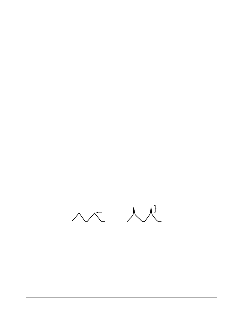
The saturation characteristics may be checked with the
inductor wired into the switching regulator application
circuit. To do so, build and power up the circuit. Then clamp
an oscilloscope current probe (recommend Tektronix P6042
or equivalent) around the inductor lead and monitor the cur-
rent in the inductor. Draw the maximum load current from
the application circuit so that the regulator is running at close
to full duty cycle. Compare the waveform you see to those
pictured.
Check for saturation at the highest expected ambient
temperature.
7. After the operation in circuit has been checked,
reassemble and pot the core using a potting compound
recommended by the manufacturer.
If the core material differs greatly in magnetic
characteristics from the standard power material shown
in Figure 16, then the following general equation can be
used to help in winding and gapping. This equation can
be used for any core geometry, such as an E-E core.
Where:
N = number of turns
Ae = core area from data sheet (in cm2)
le = magnetic path length from data sheet (in cm)
ue =permeability of core from manufacturer's graph
g = center post air gap (in cm)
Manufacturers
Below is a list of several pot core manufacturers:
Ferroxcube Company
5083 Kings Highway
Saugerties, NY 12477
Indiana General Electronics
Keasley, NJ 08832
Siemens Company
186 Wood Avenue South
Iselin, NJ 08830
Stackpole Company
201 Stackpole Street
St. Mary, PA 15857
TDK Electronics
13-1, 1-Chrome
Nihonbaski, Chuo-ku, Tokyo
L
X
-1.26
(
)
N
2
(
g
=
)
Ae
(
le/ue
)
10
8
(
)
)
(
=
Figure 23. Inductor Current Waveforms
0
I
MAX
65-3464-08
Proper Operation
(Waveform is Fairly Linear)
Improper Operation
(Waveform is Nonlinear, Inductor
Is Saturating)
0
I
MAX
相關(guān)PDF資料 |
PDF描述 |
|---|---|
| RC4391N | Inverting and Step-Down Switching Regulator |
| RC4558 | Dual High-Gain Operational Amplifier |
| RC4558JG | DUAL GENERAL-PURPOSE OPERATIONAL AMPLIFIERS |
| RC4558PS | DUAL GENERAL-PURPOSE OPERATIONAL AMPLIFIERS |
| RC4558DBR | DUAL GENERAL-PURPOSE OPERATIONAL AMPLIFIERS |
相關(guān)代理商/技術(shù)參數(shù) |
參數(shù)描述 |
|---|---|
| RC4391N | 制造商:FAIRCHILD 制造商全稱:Fairchild Semiconductor 功能描述:Inverting and Step-Down Switching Regulator |
| RC4391Z WAF | 制造商:Fairchild Semiconductor Corporation 功能描述: |
| RC4460-34GA4 | 制造商:Electronic Hardware Corporation (EHC) 功能描述:RC4460-34GA4 |
| RC446-147 | 制造商: 功能描述: 制造商:undefined 功能描述: |
| RC45 | 制造商:Thomas & Betts 功能描述:TENSION SPLICE 制造商:Thomas & Betts 功能描述:Splice Terminal 4AWG 304.8mm |
發(fā)布緊急采購,3分鐘左右您將得到回復(fù)。