- 您現(xiàn)在的位置:買賣IC網(wǎng) > PDF目錄358333 > RBC-12/25-D48PB-C (CD TECHNOLOGIES INC) 1-OUTPUT DC-DC REG PWR SUPPLY MODULE PDF資料下載
參數(shù)資料
| 型號: | RBC-12/25-D48PB-C |
| 廠商: | CD TECHNOLOGIES INC |
| 元件分類: | 電源模塊 |
| 英文描述: | 1-OUTPUT DC-DC REG PWR SUPPLY MODULE |
| 封裝: | ROHS COMPLIANT, PACKAGE-5 |
| 文件頁數(shù): | 4/6頁 |
| 文件大小: | 155K |
| 代理商: | RBC-12/25-D48PB-C |
RBC Series
R E G U L A T E D D C / D C B U S C O N V E R T E R S
RBC Series
Page 4 of 6
www.cd4power.com
T E C H N I C A L N O T E S
I/O Filtering and Noise Reduction
The RBC-12/25-D48 is tested and specified with external output capacitors.
These capacitors are necessary to accommodate our test equipment and
may not be required to achieve desired performance in your application. The
RBC-12/25-D48 is designed with high-quality, high-performance
internal
I/O
caps, and will operate within spec in most applications with
no additional
external components
.
In particular, the RBC-12/25-D48 input capacitors are specified for low ESR
and are fully rated to handle the units' input ripple currents. Similarly, the
internal output capacitors are specified for low ESR and full-range frequency
response.
In critical applications, input/output ripple/noise may be further reduced using
filtering techniques, the simplest being the installation of external I/O caps.
External input capacitors serve primarily as energy-storage devices. They
minimize high-frequency variations in input voltage (usually caused by IR
drops in conductors leading to the DC/DC) as the switching converter draws
pulses of current. Input capacitors should be selected for bulk capacitance
(at appropriate frequencies), low ESR, and high rms-ripple-current ratings.
The switching nature of modern DC/DC's requires that the dc input voltage
source have low ac impedance at the frequencies of interest. Highly inductive
source impedances can greatly affect system stability. Your specific system
configuration may necessitate additional considerations.
#
).
6
).
#
"53
,
"53
#
).
§&%32M
#
"53
§&%32M
,
"53
§(
7
K(Z
7
K(Z
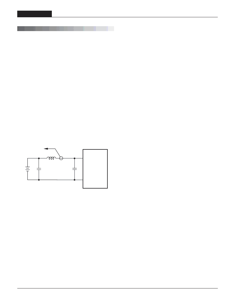
).054
#/--/.
#522%.4
02/"%
4/
/3#),,/3#/0%
n
Figure 2. Measuring Input Ripple Current
Output Reverse Conduction
Many DC/DC's using synchronous rectification suffer from Output Reverse
Conduction. If those devices have a voltage applied across their output before
a voltage is applied to their input (this typically occurs when another power
supply starts before them in a power-sequenced application), they will either
fail to start or self destruct. In both cases, the cause is the "freewheeling" or
"catch" FET biasing itself on and effectively becoming a short circuit.
The RBC-12/25-D48 will withstand higher external sources several volts
above the nominal output. However, if there is a chance of consistent over-
voltage, users should provide an external voltage clamp or other protection.
Input Fusing
Most applications and or safety agencies require the installation of fuses at
the inputs of power conversion components. The RBC-12/25-D48 Series may
have an optional input fuse. Therefore, if input fusing is mandatory, either
a normal-blow or a fast-blow fuse with a value no greater than twice the
maximum input current should be installed within the ungrounded input path
to the converter.
As a rule of thumb however, we recommend to use a normal-blow or slow-
blow fuse with a typical value of about twice the maximum input current,
calculated at low line with the converter's minimum efficiency.
Input Overvoltage and Reverse-Polarity Protection
The RBC-12/25-D48 does not incorporate input reverse-polarity protection.
Input voltages in excess of the specified absolute maximum ratings and input
polarity reversals of longer than "instantaneous" duration can cause perma-
nent damage to these devices.
Start-Up Time
The V
IN
to V
OUT
Start-Up Time is the interval between the time at which a
ramping input voltage crosses the lower limit of the specified input voltage
range and the fully loaded output voltage enters and remains within its
specified accuracy band. Actual measured times will vary with input source
impedance, external input capacitance, and the slew rate and final value of
the input voltage as it appears to the converter.
The On/Off to V
OUT
Start-Up Time assumes the converter is turned off via
the On/Off Control with the nominal input voltage already applied to the con-
verter. The specification defines the interval between the time at which the
converter is turned on and the fully loaded output voltage enters and remains
within its specified accuracy band.
相關(guān)PDF資料 |
PDF描述 |
|---|---|
| RBU1506M-HF | 15 A, 800 V, SILICON, BRIDGE RECTIFIER DIODE |
| RBU1501M-C | 15 A, 50 V, SILICON, BRIDGE RECTIFIER DIODE |
| RBU1506M | 15 A, 800 V, SILICON, BRIDGE RECTIFIER DIODE |
| RBV-404 | 4 A, 400 V, SILICON, BRIDGE RECTIFIER DIODE |
| RBV-602 | 6 A, 200 V, SILICON, BRIDGE RECTIFIER DIODE |
相關(guān)代理商/技術(shù)參數(shù) |
參數(shù)描述 |
|---|---|
| RBC124 | 制造商:American Power Conversion Corp (APC by Schneider Electric) 功能描述:Replacement Battery Cartridge # 124 |
| RBC1257 | 制造商:Thomas & Betts 功能描述:TERM, RBC INSUL ASSY |
| RBC12A | 功能描述:密封鉛酸電池 12V REPLACEMENT BATTERY CARTRIDGE RoHS:否 制造商:CSB 輸出電壓:12 V 容量: 大小: 端接類型:Faston Tab |
| RBC-12-D48 | 制造商:MURATA-PS 制造商全稱:Murata Power Solutions Inc. 功能描述:Quarter Brick, Regulated Bus Converters |
| RBC-12-D48NB-C | 制造商:MURATA-PS 制造商全稱:Murata Power Solutions Inc. 功能描述:Quarter Brick, Regulated Bus Converters |
發(fā)布緊急采購,3分鐘左右您將得到回復(fù)。