- 您現(xiàn)在的位置:買賣IC網(wǎng) > PDF目錄371968 > R485 R485-Type Lightwave Receiver with Clock Recovery for 2.488 Gbits/s Applications PDF資料下載
參數(shù)資料
| 型號(hào): | R485 |
| 英文描述: | R485-Type Lightwave Receiver with Clock Recovery for 2.488 Gbits/s Applications |
| 中文描述: | R485型光波接收機(jī)2.488磁錄密度/有時(shí)鐘恢復(fù)s應(yīng)用 |
| 文件頁(yè)數(shù): | 2/10頁(yè) |
| 文件大?。?/td> | 134K |
| 代理商: | R485 |
2
Agere Systems Inc.
Advance Data Sheet, Rev. 1
October 2001
Recovery for 2.488 Gbits/s Applications
R485-Type Lightwave Receiver with Clock
Flag Output
When the incoming optical signal falls below the link-
status switching threshold, the FLAG output is asserted
and the FLAG output logic level changes from a TTL
low to a TTL high.
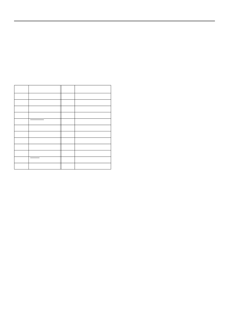
Pin Information
Table 1. Pin Information
* Pins designated as no user connect (NUC) are connected inter-
nally. The user should not make any connections to these pins.
The loss of signal (LOS) FLAG output is a logic level that indicates
the presence or absence of a minimum acceptable level of optical
input. A TTL logic HIGH indicates the absence of a valid optical
input signal.
This pin is not internally connected if the amplitude decision
threshold (DTV) is not made adjustable.
Handling Precautions
The R485-Type receiver is manufactured with a
39 in.
±
4 in. (100 cm
±
10 cm) single-mode fiber pigtail
with a 900
μ
m OD PVC outer jacket. Both SC and FC-
PC connectors are offered on standard versions. Other
optical connector options are available on special
order. Please contact an Agere Systems Account Man-
ager for availability and ordering information.
The minimum fiber bending radius is 1.5 inches
(38 mm).
Receiver Processing
The R485-Type receiver devices can withstand normal
wave soldering processes. The complete receiver mod-
ule is not hermetically sealed; therefore, it should not
be immersed in, or sprayed with, any solutions. The
optical connector process cap deformation temperature
is 85
°
C. The receiver pins can be wave soldered at
250
°
C for 10 seconds.
Electrostatic Discharge
CAUTION: This device is susceptible to damage as
a result of electrostatic discharge (ESD).
Take proper precautions during both
handling and testing. Follow guidelines
such as JEDEC Publication No. 108-A
(Dec. 1988).
Although protection circuitry is designed into the
device, take proper precautions to avoid exposure to
ESD.
Agere employs a human-body model HBM) for ESD-
susceptibility testing and protection design evaluation.
ESD voltage thresholds are dependent on the critical
parameters used to define the model. A standard HBM
(resistance = 1.5 k
, capacitance = 100 pF) is widely
used and, therefore, can be used for comparison pur-
poses.
Installation Considerations
Although the receiver has been designed with rugged-
ness in mind, care should be used during handling.
The optical connector should be kept free from dust.
The optical connector process cap should be kept in
place as a dust cover when the device is not connected
to a cable. If contamination is present on the optical
connector, the use of canned air with a extension tube
should remove any loose debris. Other cleaning proce-
dures are outlined in the Cleaning Fiber Optic Assem-
bliesTechnical Note (TN95-010LWP).
The cable should be handled conservatively with no
excessive axial pulling or lateral tugging.
Pin
Name
Pin
Name
1
2
3
4
5
6
7
8
9
10
11
12
NIC
NUC*
LOS Flag
Ground
CLOCK
CLOCK
Ground
V
CC
Ground
DATA
DATA
Ground
24
23
22
21
20
19
18
17
16
15
14
13
NUC*
NUC*
V
CC
NUC*
Ground
Ground
NIC
Ground
Ground
Ground
Ground
DTV/NIC
相關(guān)PDF資料 |
PDF描述 |
|---|---|
| R485WPBB | DIODE ZENER SINGLE 200mW 16.1Vz 10mA-Izt 0.02547 0.05uA-Ir 12 SOD-323 3K/REEL |
| R485WPAA | R485-Type Lightwave Receiver with Clock Recovery for 2.488 Gbits/s Applications |
| R485CMAA | R485-Type Lightwave Receiver with Clock Recovery for 2.488 Gbits/s Applications |
| R485CPAA | R485-Type Lightwave Receiver with Clock Recovery for 2.488 Gbits/s Applications |
| R485CPBB | R485-Type Lightwave Receiver with Clock Recovery for 2.488 Gbits/s Applications |
相關(guān)代理商/技術(shù)參數(shù) |
參數(shù)描述 |
|---|---|
| R4850-T2D512 | 制造商:Micro-Star International 功能描述:MSI HD 4850, 512MB - Bulk |
| R4858446-18 | 制造商:n/a 功能描述:Power Module |
| R48-5A5-120 | 制造商:NTE Electronics 功能描述:RELAY-5AMP-A/C 120V |
| R485CMAA | 制造商:AGERE 制造商全稱:AGERE 功能描述:R485-Type Lightwave Receiver with Clock Recovery for 2.488 Gbits/s Applications |
| R485CPAA | 制造商:AGERE 制造商全稱:AGERE 功能描述:R485-Type Lightwave Receiver with Clock Recovery for 2.488 Gbits/s Applications |
發(fā)布緊急采購(gòu),3分鐘左右您將得到回復(fù)。