- 您現(xiàn)在的位置:買(mǎi)賣(mài)IC網(wǎng) > PDF目錄374547 > R1307 (Hamamatsu Photonics) CA3102E32A10SB04 PDF資料下載
參數(shù)資料
| 型號(hào): | R1307 |
| 廠商: | Hamamatsu Photonics |
| 英文描述: | CA3102E32A10SB04 |
| 中文描述: | 光電倍增管 |
| 文件頁(yè)數(shù): | 3/4頁(yè) |
| 文件大?。?/td> | 32K |
| 代理商: | R1307 |
NOTES
1: Voltage distribution ratio
Electrodes
Distribution
Ratio
Supply voltage (Ebb) = 1000Vdc
K: cathode, G: Focusing Electrode, Dy: Dynode, P: Anode
Scintillator is manufactured by Harshaw Chemical, (Type 12A12), and
BICRON (Type 3R3), Nal (Tl), 3" diameter 3" thickness.
Drift for 1 hour after 10 minutes of initial warming up with 10
μ
A anode
current.
A
137
Cs source and an Nal (Tl) crystal are employed to measure the
pulse height. Warming up time is about 1 hour.
a) Long term (Mean Gain Deviation) is defined as follows.
n
i
100
P
n
2.
3.
4.
where P is the mean pulse height averaged over n readings, P
i
is the
pulse height at the i-th reading, and n is the total number of readings.
b) Short term
Scintillator (Nal (Tl) crystal) is 3" diameter 3" thickness. The photomul-
tiplier is first operated at about 10,000 cps. The photopeak counting
is then decreased to approximately 1,000 cps by increasing the dis-
tance between source and crystal on the tube.
5. Averaged over any interval of 30 seconds maximum.
6. Same as Note 5 and the whole photocathode is illuminated.
7.
The light source is a tungsten filament lamp operated at a distribution
temperature of 2856K. The light input of 10
-7
lumen is used.
8.
The value is anode output current when the blue filter (Corning CS 5-58
polished to 1/2 stock thickness) is interposed between the light source
(providing 10
-7
lumen) and the tube under the same condition as Note 7.
9.
The condition is the same shown in Note 7 except that the value of light
input is 10
-4
limen and 150 volts are applied between cathode and all oth-
er electrodes connected together as anode.
10. These values are cathode output current when the blue filter (Corning
CS 5-58 polished to 1/2 stock thickness) is interposed between the light
source (providing 10
-4
lumen) and the tube under the same condition as
Note 9.
11. Measured after 5-second strage in the dark.
12. The rise time is the time for the output pulse to rise from 10% to 90% of
the peak output when the tube is illuminated by a flash of light of very
short duration. In measurement, the whole photocathode is illuminated.
13. The electron transit time is the interval between the arrival of delta func-
tion light pulse at the entrance window of the tube and the time when the
output pulse at the anode terminal reaches peak amplitude.
14. m is the mean value of total counts, i.e.
(counts per channel) =
Σ
(counts per channel)
0.3m
m
Test conditions: Incident light wavelength is 400nm. Supply voltage is
+1300V. Ambient temperature is 20
°
C.
K
Dy1
G
1
Dy2
1
Dy3
1
Dy4
1
Dy5
1
Dy6
1
Dy7
1
Dy8
1
1
1
P
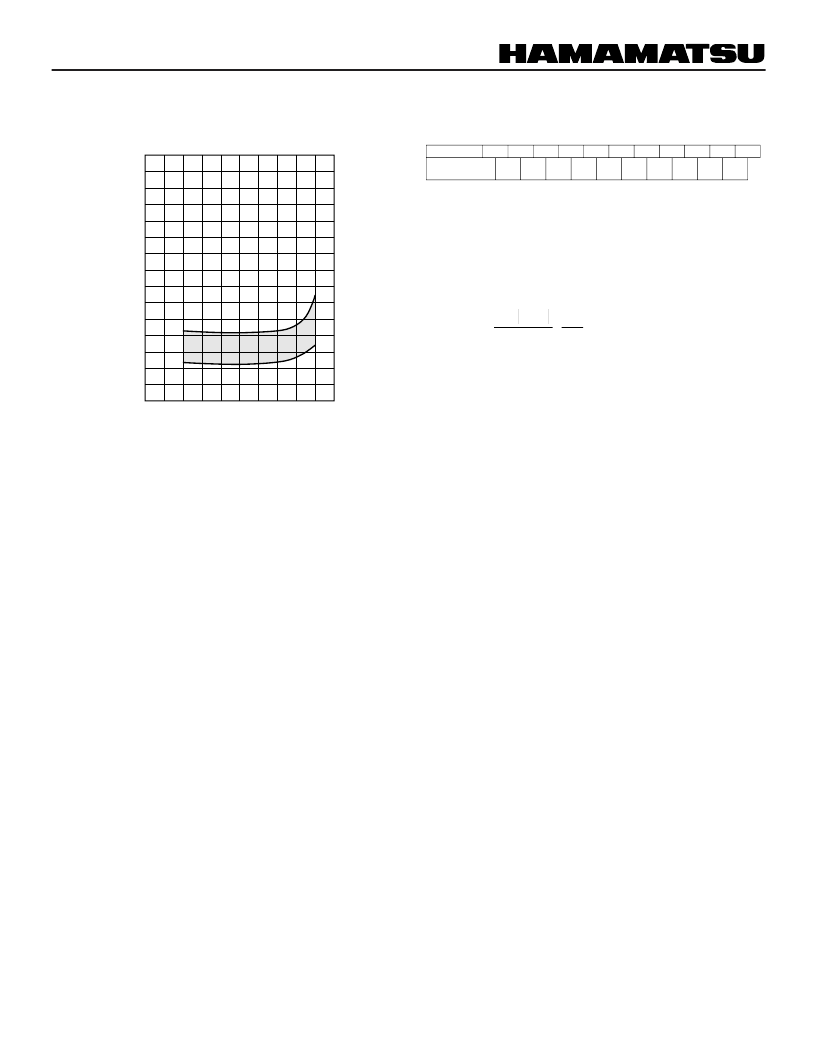
Figure 5: Typical Temperature Coefficient of Anode
Sensitivity
(-20 to +60
°
C, Note 1)
TPMHB0527EA
200
300
400
500
600
700
0
-1.0
+2.0
WAVELENGTH (nm)
T
°
C
+1.0
Dg = P - P
m
3m
相關(guān)PDF資料 |
PDF描述 |
|---|---|
| R1307-01 | PHOTOMULTIPLIER TUBES |
| R1387 | PHOTOMULTlPLlER TUBE |
| R145-32.768-8 | TUNING FORK CRYSTAL UNIT |
| R1450 | PHOTOMULTIPLIER TUBE |
| R145 | TUNING FORK CRYSTAL UNITS |
相關(guān)代理商/技術(shù)參數(shù) |
參數(shù)描述 |
|---|---|
| R1307-01 | 制造商:HAMAMATSU 制造商全稱(chēng):Hamamatsu Corporation 功能描述:PHOTOMULTIPLIER TUBES |
| R13072 | 制造商:Esico Triton 功能描述:Power Unit W/R12077 Handpiece |
| R13072-230 | 制造商:Esico Triton 功能描述:(POWER UNIT PLUS CABLES PLUS PLIERS |
| R13094 | 制造商:Esico Triton 功能描述:Power Unit W/R12067 Handpiece |
| R1309P012 | 制造商: 功能描述: 制造商:undefined 功能描述: |
發(fā)布緊急采購(gòu),3分鐘左右您將得到回復(fù)。