- 您現(xiàn)在的位置:買賣IC網(wǎng) > PDF目錄98065 > PTH12040WAST (TEXAS INSTRUMENTS INC) 1-OUTPUT DC-DC REG PWR SUPPLY MODULE PDF資料下載
參數(shù)資料
| 型號: | PTH12040WAST |
| 廠商: | TEXAS INSTRUMENTS INC |
| 元件分類: | 電源模塊 |
| 英文描述: | 1-OUTPUT DC-DC REG PWR SUPPLY MODULE |
| 封裝: | DIP-20 |
| 文件頁數(shù): | 5/27頁 |
| 文件大小: | 633K |
| 代理商: | PTH12040WAST |
第1頁第2頁第3頁第4頁當前第5頁第6頁第7頁第8頁第9頁第10頁第11頁第12頁第13頁第14頁第15頁第16頁第17頁第18頁第19頁第20頁第21頁第22頁第23頁第24頁第25頁第26頁第27頁
Adjusting the Undervoltage Lockout (UVLO) of the PTH12040W Power Modules
UVLO Adjustment
Adjustment Method
PTH12040W
2
4
6
7
8 UVLOProg
Inhibit
GND
1
3
5
V
I
C
I
1000 F
m
V
I
R
HYS
R
THD
www.ti.com............................................................................................................................................... SLTS237G – DECEMBER 2004 – REVISED MARCH 2009
The PTH12040W power modules incorporate an input undervoltage lockout (UVLO). The UVLO feature prevents
the operation of the module until there is sufficient input voltage to produce a valid output voltage. This enables
the module to provide a clean, monotonic powerup for the load circuit, and also limits the magnitude of current
drawn from the regulator’s input source during the power-up sequence.
The UVLO characteristic is defined by the on-threshold (VTHD) and hysterisis (VHYS) voltages. Below the on
threshold, the Inhibit control is overriden, and the module does not produce an output. The hysterisis voltage is
the difference between the on and off threshold voltages. It ensures a clean power-up, even when the input
voltage is rising slowly. The hysterisis prevents start-up oscillations, which can occur if the input voltage droops
slightly when the module begins drawing current from the input source.
The UVLO feature of the PTH12040W module allows for limited adjustment of both the on threshold and
hysterisis voltages. The adjustment is made via the UVLO Prog control pin. When the UVLO Prog pin is left open
circuit, the on threshold and hysterisis voltages are internally set to their default values. The on threshold has a
nominal voltage of 7.5 V, and the hysterisis 1 V. This ensures that the module produces a regulated output when
the minimum input voltage is applied (see specifications). The combination correlates to an off threshold of
approximately 6.5 V. The adjustments are limited. The on threshold can only be adjusted higher, and the
hysterisis voltage can only be reduced in magnitude.
The on threshold might need to be raised if the module is powered from a tightly regulated 12-V bus. This would
prevent it from operating if the input bus failed to completely rise to its specified regulation voltage. The hysterisis
should not be changed unless absolutely necessary. A generous amount of hysterisis ensures that the module
exhibits a clean startup. Therefore, adjustment of the hysterisis should only be considered if there is a system
requirement to specifically set the off threshold voltage (in addition to the on threshold). Depending on the load
regulation of the input source, the hysterisis should not be adjusted below 0.5 V without careful consideration.
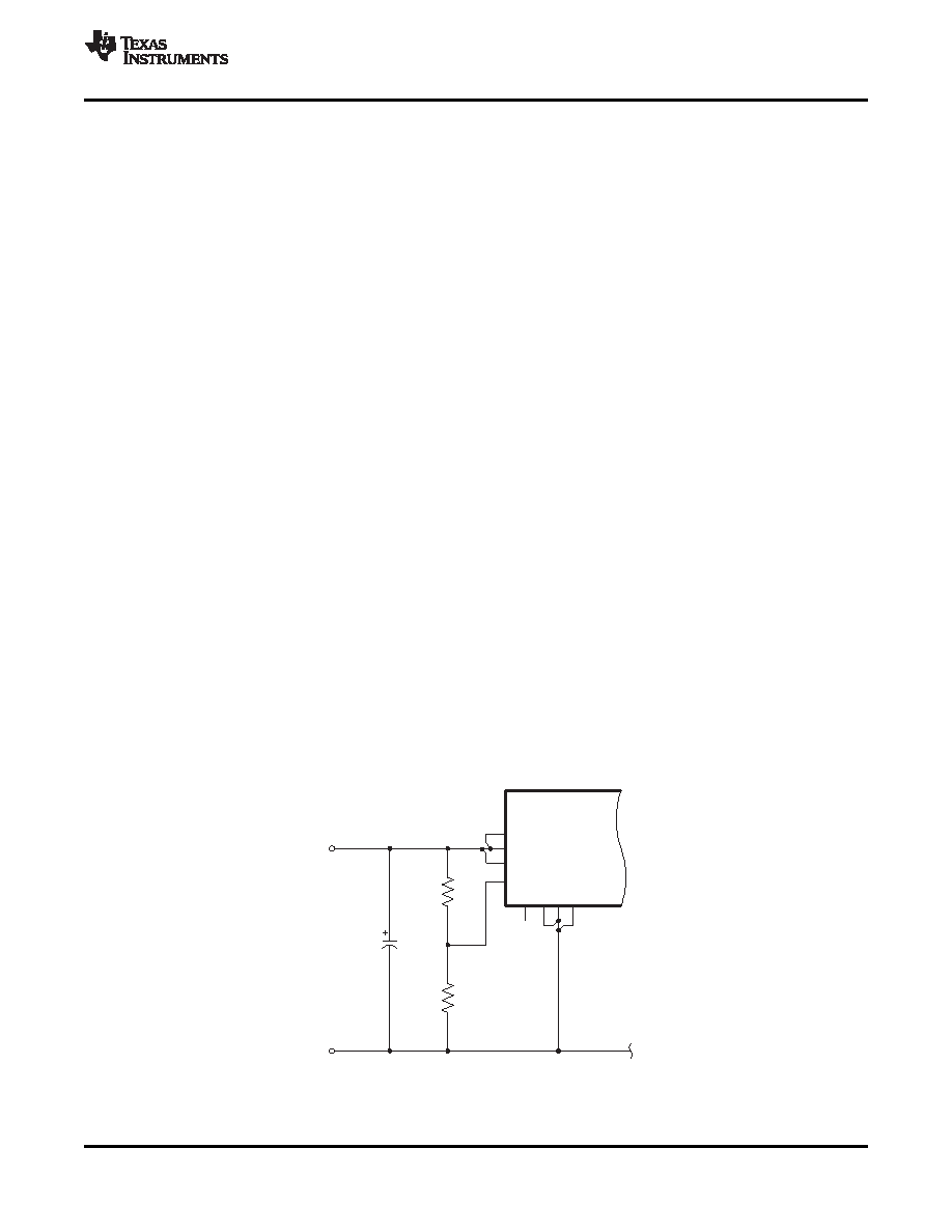
The resistors, RTHD and RHYS (see Figure 9), provide the adjustment of the on-threshold and hysterisis voltages.
RTHD connects between the UVLO Prog control pin and GND, and RHYS is connected between the UVLO Prog
and VI. RTHD alone is used to adjust the on-threshold voltage higher. However, to adjust the hystersis to a lower
value requires both the RHYS and RTHD resistors to be placed in the circuit.
The recommended adjustment method requires that any change to the hysterisis be determined first. If the
hysterisis is changed, then a value for RTHD must also be calculated. This is irrespective of whether a change is
required to the value of VTHD. If there is no change to VHYS, then a resistor should not be placed in the RHYS
location. RHYS should then be assigned an infinite value for calculating the value of RTHD.
Figure 9. UVLO Program Resistor Placement
Copyright 2004–2009, Texas Instruments Incorporated
13
Product Folder Link(s): PTH12040W
相關(guān)PDF資料 |
PDF描述 |
|---|---|
| PTH12040WAH | 1-OUTPUT DC-DC REG PWR SUPPLY MODULE |
| PTH12040WAZ | 1-OUTPUT DC-DC REG PWR SUPPLY MODULE |
| PTN04050AAST | 1 A SWITCHING REGULATOR, 310 kHz SWITCHING FREQ-MAX, PDMA5 |
| PTN04050AAD | 1 A SWITCHING REGULATOR, 310 kHz SWITCHING FREQ-MAX, PDMA5 |
| PTN04050AAZT | 1 A SWITCHING REGULATOR, 310 kHz SWITCHING FREQ-MAX, PDMA5 |
相關(guān)代理商/技術(shù)參數(shù) |
參數(shù)描述 |
|---|---|
| PTH12040WAZ | 功能描述:DC/DC轉(zhuǎn)換器 8.0-14Vin 5.5V 50A 2.045" x1.045"x0.357 RoHS:否 制造商:Murata 產(chǎn)品: 輸出功率: 輸入電壓范圍:3.6 V to 5.5 V 輸入電壓(標稱): 輸出端數(shù)量:1 輸出電壓(通道 1):3.3 V 輸出電流(通道 1):600 mA 輸出電壓(通道 2): 輸出電流(通道 2): 安裝風(fēng)格:SMD/SMT 封裝 / 箱體尺寸: |
| PTH12040WAZT | 功能描述:DC/DC轉(zhuǎn)換器 8.0-14Vin 5.5V 50A 2.045" x1.045"x0.357 RoHS:否 制造商:Murata 產(chǎn)品: 輸出功率: 輸入電壓范圍:3.6 V to 5.5 V 輸入電壓(標稱): 輸出端數(shù)量:1 輸出電壓(通道 1):3.3 V 輸出電流(通道 1):600 mA 輸出電壓(通道 2): 輸出電流(通道 2): 安裝風(fēng)格:SMD/SMT 封裝 / 箱體尺寸: |
| PTH12045WAD | 制造商:Texas Instruments 功能描述: |
| PTH12045WAZ | 制造商:Texas Instruments 功能描述:- Rail/Tube |
| PTH12050 | 制造商:EMERSON-NETWORKPOWER 制造商全稱:Emerson Network Power 功能描述:DC-DC CONVERTERS |
發(fā)布緊急采購,3分鐘左右您將得到回復(fù)。