- 您現(xiàn)在的位置:買賣IC網(wǎng) > PDF目錄66056 > PT6915N (TEXAS INSTRUMENTS INC) 1-OUTPUT 12 W DC-DC REG PWR SUPPLY MODULE PDF資料下載
參數(shù)資料
| 型號: | PT6915N |
| 廠商: | TEXAS INSTRUMENTS INC |
| 元件分類: | 電源模塊 |
| 英文描述: | 1-OUTPUT 12 W DC-DC REG PWR SUPPLY MODULE |
| 封裝: | VERTICAL THROUGH HOLE-23 |
| 文件頁數(shù): | 1/7頁 |
| 文件大小: | 130K |
| 代理商: | PT6915N |
For technical support and more information, see inside back cover or visit www.ti.com/powertrends
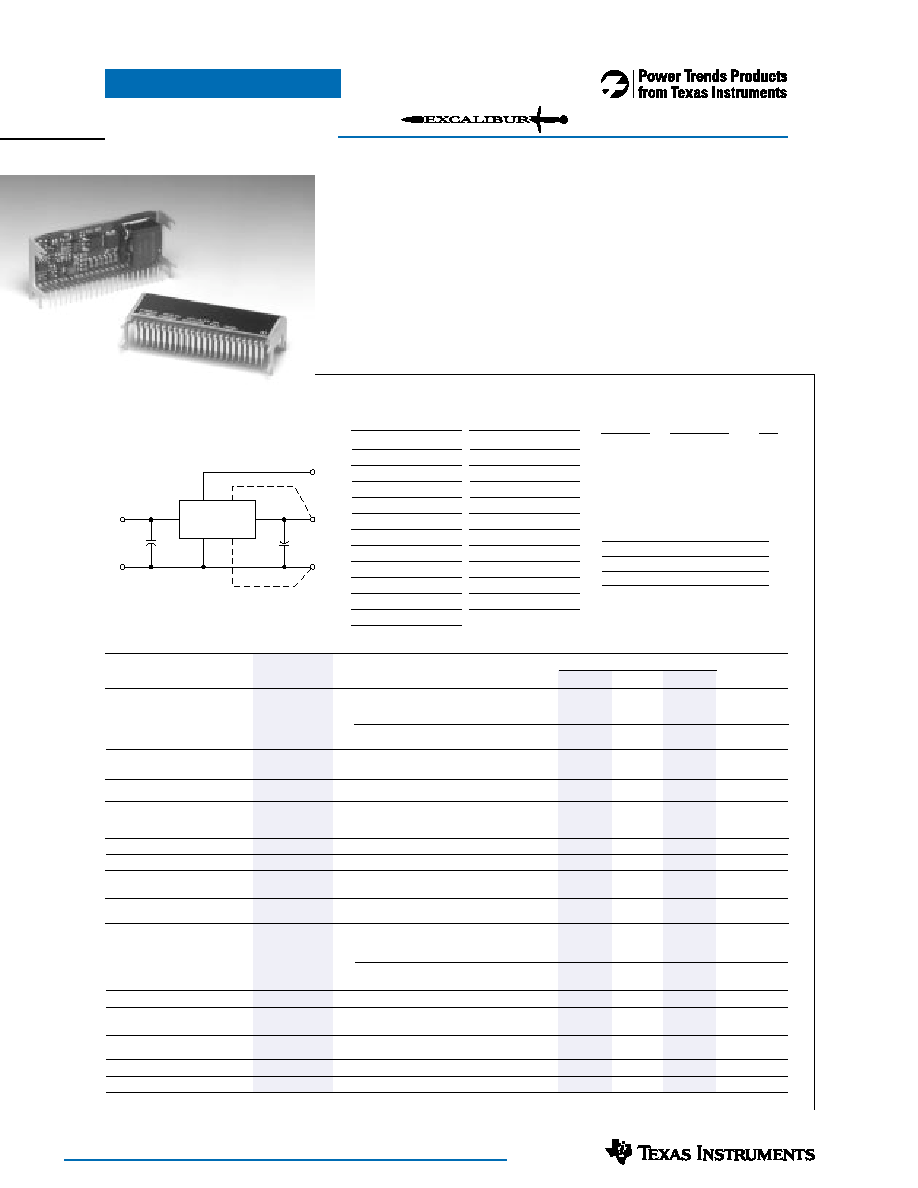
PT6910 Series
Standard Application
Ordering Information
+5V Input
+3.3V Input
Vout
PT6911
o PT6914q = –2.0V
PT6912
o PT6915q = –5.2V
PT6913
q
= –1.5V
Cin = Required 330F electrolytic
Cout = Required 330F electrolytic
Single-Device: +5V/3.3V input
Remote Sense
+5V & +3.3V Input Voltage
Adjustable Output Voltage
23-pin Space-Saving Package
Solderable Copper Case
The PT6910 series is a series of
high performance 12 watt, plus to minus
voltage convertors that are designed to
power the latest ECL (–5.2V) and
Pin Function
1
Do not connect
2Vout Adjust
3Vin
4Vin
5Vin
6Vin
7Vin
8
Remote Sense GND
9
GND
10
GND
11
GND
12
GND
Pin
Function
13
GND
14
GND
15
GND
16
Vout
17
Vout
18
Vout
19
Vout
20
Vout
21
Vout
22
Remote Sense Vout
23
Do not connect
Pin-Out Information
GaAs (-2.0V) ICs from an existing
+5.0V or +3.3V source.
These regulators are similar to
the popular PT6900 series with the
added feature of Power Trends’ unique
solderable copper case.
A 330F electrolytic capacitor is
required on both the input and output
for proper operation. Also note that
this product does not include short-
circuit protection.
(For dimensions and PC board layout,
see Package Styles 1300 and 1310.)
Cout
Cin
PT6900
16-21
9-15
3-7
2
V
ADJ
-V
OUT
GND
+V
IN
+
22
Remote Sense
8
PT Series Suffix (PT1234X)
Case/Pin
Configuration
Vertical Through-Hole
N
Horizontal Through-Hole
A
Horizontal Surface Mount
C
PT6910
Specifications
Characteristics
PT6910 SERIES
(Ta= 25°C unless noted)
Symbols
Conditions
Min
Typ
Max
Units
Output Current
Io
Ta = +25°C, natural convection
Vin =5.0V
Vo = –2.0V / –1.5V
0.1 (1)
—
6.0 (2)
A
Vo = –5.2V
0.1 (1)
—
3.5 (2)
Vin =3.3V
Vo = –2.0V
0.1 (1)
—
5.0 (2)
A
Vo = –5.2V
0.1 (1)
—
2.5 (2)
A
Input Voltage Range
0.1A
≤ Io ≤ Imax
PT6911 PT6912/PT6913
4.5
—
5.5
PT6914/PT6915
3.1
—
3.6
V
Output Voltage Tolerance
Vo
Nominal Vin, Io = Imax
Vo – 0.05
—
Vo + 0.05
V
0°C
≤ Ta ≤ +60°C
Output Adjust Range
Vo
Pin 14 to Vo or GND
Vo = –2.0V
–1.4
—
–4.4
Vo = –5.2V
–2.7
—
–6.5
V
Vo = –1.5V
–1.2
—
–3.4
Line Regulation
Regline
Over Vin range, Io =Imax
—
±0.5
±1.0
%
Load Regulation
Regload
Vin =Vnom, 0.1 ≤ Io ≤ Imax
—
±0.5
±1.0
%
Vo Ripple/Noise
Vn
Vin = Vnom, Io =Imax
Vo = –1.5V / –2.0V
—
40
—
mV
Vo = –5.2V
—
50
—
Transient Response
ttr
Io step between 0.5xImax and Imax
—
200
—
Sec
with Cout = 330F
Vos
Vo over/undershoot
—
200
—
mV
Efficiency
η
Vin =+5V, Io =0.5xImax
Vo = –1.5V
—
65
—
Vo = –2.0V
—
70
—
%
Vo = –5.2V
—
77
—
Vin = +3.3V, Io =0.5xImax
Vo = –2.0V
—
67
—
%
Vo = –5.2V
—
75
—
Switching Frequency
o
Over Vin and Io ranges
500
—
600
kHz
Absolute Maximum
Ta
0
—
+85 (2)
°C
Operating Temperature Range
Recommended Operating
Ta
Over Vin Range
0
—
+60
°C
Temperature Range
Storage Temperature
Ts
-40
—
+125
°C
Weight
—
Vertical/Horizontal
—
26
—
grams
Notes:
(1) ISR-will operate down to no load with reduced specifications.
(2) See Safe Operating Area curves, or consult the factory for the appropriate derating.
Patent pending on package assembly
12 Watt 5V/3.3V Input
Plus to Minus Voltage Converter
SLTS113
(Revised 11/30/2000)
相關(guān)PDF資料 |
PDF描述 |
|---|---|
| PT6921A | SWITCHING REGULATOR, SMA23 |
| PT6921N | SWITCHING REGULATOR, SMA23 |
| PT6922C | SWITCHING REGULATOR, SMA23 |
| PT6921C | SWITCHING REGULATOR, SMA23 |
| PT6922N | SWITCHING REGULATOR, SMA23 |
相關(guān)代理商/技術(shù)參數(shù) |
參數(shù)描述 |
|---|---|
| PT6920 | 制造商:TI 制造商全稱:Texas Instruments 功能描述:5V TO 3.3V/2.5V 25 WATT DUAL OUTPUT INTEGRATED SWITCHING REGULATOR |
| PT6921 | 制造商:TI 制造商全稱:Texas Instruments 功能描述:5V TO 3.3V/2.5V 25 WATT DUAL OUTPUT INTEGRATED SWITCHING REGULATOR |
| PT6921A | 功能描述:DC/DC轉(zhuǎn)換器 3.3/2.5Vout 25W 5Vin Adj Dual Output ISR RoHS:否 制造商:Murata 產(chǎn)品: 輸出功率: 輸入電壓范圍:3.6 V to 5.5 V 輸入電壓(標(biāo)稱): 輸出端數(shù)量:1 輸出電壓(通道 1):3.3 V 輸出電流(通道 1):600 mA 輸出電壓(通道 2): 輸出電流(通道 2): 安裝風(fēng)格:SMD/SMT 封裝 / 箱體尺寸: |
| PT6921C | 功能描述:DC/DC轉(zhuǎn)換器 3.3/2.5Vout 25W 5Vin Adj Dual Output ISR RoHS:否 制造商:Murata 產(chǎn)品: 輸出功率: 輸入電壓范圍:3.6 V to 5.5 V 輸入電壓(標(biāo)稱): 輸出端數(shù)量:1 輸出電壓(通道 1):3.3 V 輸出電流(通道 1):600 mA 輸出電壓(通道 2): 輸出電流(通道 2): 安裝風(fēng)格:SMD/SMT 封裝 / 箱體尺寸: |
| PT6921N | 功能描述:DC/DC轉(zhuǎn)換器 3.3/2.5Vout 25W 5Vin Adj Dual Output ISR RoHS:否 制造商:Murata 產(chǎn)品: 輸出功率: 輸入電壓范圍:3.6 V to 5.5 V 輸入電壓(標(biāo)稱): 輸出端數(shù)量:1 輸出電壓(通道 1):3.3 V 輸出電流(通道 1):600 mA 輸出電壓(通道 2): 輸出電流(通道 2): 安裝風(fēng)格:SMD/SMT 封裝 / 箱體尺寸: |
發(fā)布緊急采購,3分鐘左右您將得到回復(fù)。