CHAPTER 23 LOW-VOLTAGE DETECTOR
User’s Manual U16228EJ2V0UD
422
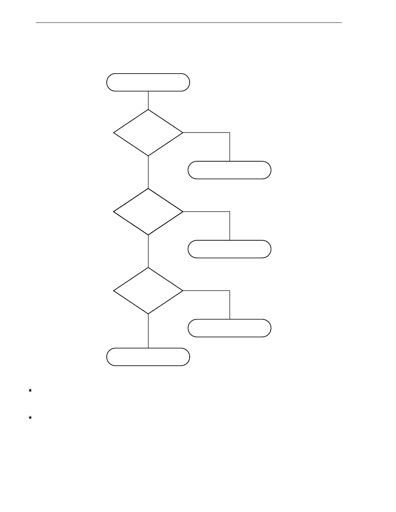
Figure 23-6. Example of Software Processing After Release of Reset (2/2)
Checking reset cause
Yes
No
Check reset cause
Power-on-clear/external
reset generated
Reset processing by
watchdog timer
Reset processing by
clock monitor
Reset processing by
low-voltage detector
No
Yes
WDTRF of RESF
register = 1
CLMRF of RESF
register = 1
LVIRF of RESF
register = 1
Yes
No
(2) When used as interrupt
Check that “supply voltage (V
DD
) > detection voltage (V
LVI
)” in the servicing routine of the LVI interrupt by using bit
0 (LVIF) of the low-voltage detection register (LVIM). Clear bit 0 (LVIIF) of interrupt request flag register 0L (IF0L)
to 0 and enable interrupts (EI).
In a system where the supply voltage fluctuation period is long in the vicinity of the LVI detection voltage, wait for
the supply voltage fluctuation period, check that “supply voltage (V
DD
) > detection voltage (V
LVI
)” using the LVIF
flag, and then enable interrupts (EI).
