- 您現(xiàn)在的位置:買賣IC網(wǎng) > PDF目錄384844 > PD55HB120 (Sanrex Corporation) CONNECTOR ACCESSORY PDF資料下載
參數(shù)資料
| 型號: | PD55HB120 |
| 廠商: | Sanrex Corporation |
| 英文描述: | CONNECTOR ACCESSORY |
| 中文描述: | 可控硅模塊 |
| 文件頁數(shù): | 1/2頁 |
| 文件大?。?/td> | 115K |
| 代理商: | PD55HB120 |
SanRex 50 Seaview Blvd. Port Washington, NY 11050-4618 PH.(516)625-1313 FAX(516)625-8845 E-mail: semi@sanrex.com
PK
(PD,PE,KK)
55HB
THYRISTOR MODULE
93.5MAX
80
2
3
1
2
K
G
110TAB
16.5
23
3
~
+
–
2
1
23
3-M5
2- 6.5
K
G
Unit
A
mark
Thyristor and Diode part. No mark
Thyristor part
Symbol
I
T AV
I
T RMS
I
TSM
I
2
t
P
GM
P
G AV
I
FGM
V
FGM
V
RGM
di
V
ISO
Tj
Tstg
Item
Conditions
Ratings
55
86
Unit
A
A
A
A
2
S
W
W
A
V
V
A
/
s
V
Average On-State Current
R.M.S. On-State Current
Surge On-State Current
I
2
t
Peak Gate Power Dissipation
Average Gate Power Dissipation
Peak Gate Current
Peak Gate Voltage (Forward)
Peak Gate Voltage (Reverse)
Critical Rate of Rise of On-State Current
Isolation Breakdown Voltage (R.M.S.)
Operating J unction Temperature
Storage Temperature
Mounting M6
Terminal
Single phase, half wave, 180 conduction, Tc
Single phase, half wave, 180 conduction, Tc
12
cycle, 50Hz
/
60Hz, peak Value, non-repetitive
Value for one cycle of surge current
85
85
1000
/
1100
5000
10
3
3
dt
I
G
A.C.1minute
100mA Tj
25
V
D
12
V
DRM
dI
G
/dt
0.1A/
s
Mounting
Torque
Mass
M5
Recommended Value 2.5-3.9
Recommended Value 1.5-2.5
25-40
15-25
10
5
150
2500
40
40
4.7
2.7
170
125
125
48
28
N
f
B
g
Symbol
I
DRM
I
RRM
V
TM
I
GT
V
GD
tgt
dv
I
H
I
L
Rth j-c
Item
Conditions
Ratings
10
10
Unit
mA
mA
V
mA
/
V
V
Repetitive Peak Off-State Current, max.
Repetitive Peak Reverse Current, max.
Peak On-State Voltage, max.
Gate Trigger Current/Voltage, max.
Non-Trigger Gate, Voltage. min.
Turn On Time, max.
Critical Rate of Rise of Off-State Voltage, min.
Holding Current, typ.
Lutching Current, typ.
Thermal Impedance, max.
at V
DRM
, single phase, half wave, Tj
at V
DRM
, single phase, half wave, Tj
On-State Current 165A, Tj
Tj
25
I
T
1A
Tj
125
V
D
I
T
55A I
G
100mA Tj 25
Tj
125
, V
D
Tj
25
Tj
25
J unction to case
125
125
V
GT
dt
125
6V
Inst. measurement
V
D
1.50
100
/
2
0.25
12
V
DRM
V
D
12
V
DRM
dI
G
/
dt 0.1A
/
s
10
23
V
DRM
, Exponential wave.
500
50
100
0.50
s
V
/
s
mA
mA
/
W
Electrical Characteristics
Maximum Ratings
Symbol
Item
PK55HB120
KK55HB120
PD55HB120
PE55HB120
1200
1350
1200
Ratings
PK55HB160
KK55HB160
PD55HB160
PE55HB160
1600
1700
1600
Unit
V
RRM
V
RSM
V
DRM
Repetitive Peak Reverse Voltage
Non-Repetitive Peak Reverse Voltage
Repetitive Peak Off-State Voltage
V
V
V
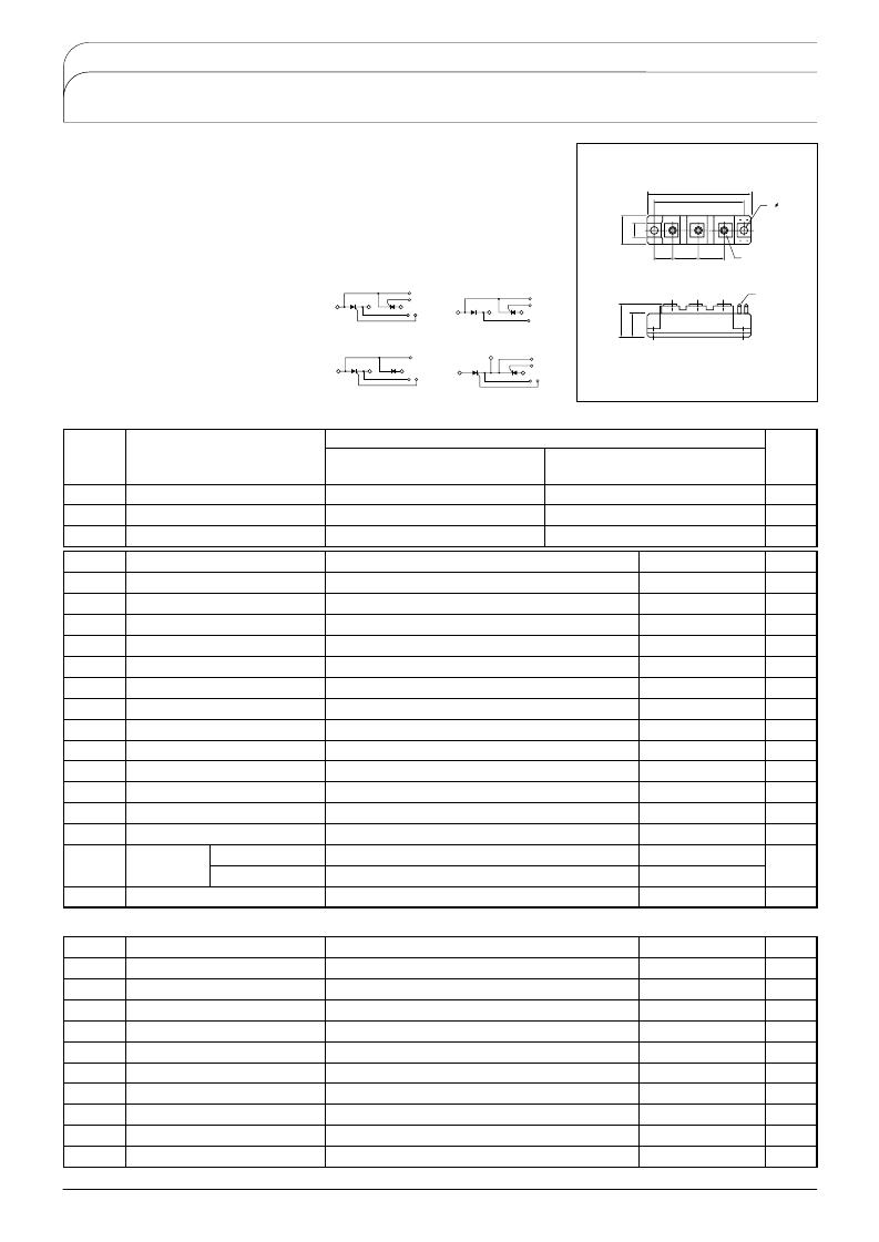
Power Thyristor/Diode Module
PK55HB
series are designed for various rectifier circuits
and power controls. For your circuit application. following internal connections and wide
voltage ratings up to 1,600V are available. and electrically isolated mounting base make
your mechanical design easy.
I
T(AV)
55A, I
T(RMS)
86A, I
TSM
1100A
di/dt 150 A/
s
dv/dt 500V/
s
Applications
Various rectifiers
AC/DC motor drives
Heater controls
Light dimmers
Static switches
Internal Configurations
UL;E76102 M
PK
PE
PD
KK
相關(guān)PDF資料 |
PDF描述 |
|---|---|
| PD57060 | RF POWER TRANSISTORS The LdmoST Plastic FAMILY |
| PD57060S | RF POWER TRANSISTORS The LdmoST Plastic FAMILY |
| PD70F120 | THRISTOR MODULE |
| PD70F160 | THRISTOR MODULE |
| PD70F40 | THRISTOR MODULE |
相關(guān)代理商/技術(shù)參數(shù) |
參數(shù)描述 |
|---|---|
| PD55HB160 | 制造商:SANREX 制造商全稱:SanRex Corporation 功能描述:THYRISTOR MODULE |
| PD57 | 制造商:未知廠家 制造商全稱:未知廠家 功能描述:Analog IC |
| PD57002 | 功能描述:射頻MOSFET電源晶體管 N-Ch 65 Volt 0.25A RoHS:否 制造商:Freescale Semiconductor 配置:Single 晶體管極性: 頻率:1800 MHz to 2000 MHz 增益:27 dB 輸出功率:100 W 汲極/源極擊穿電壓: 漏極連續(xù)電流: 閘/源擊穿電壓: 最大工作溫度: 封裝 / 箱體:NI-780-4 封裝:Tray |
| PD57002-01 | 制造商:未知廠家 制造商全稱:未知廠家 功能描述:TRANSISTOR | MOSFET | N-CHANNEL | 65V V(BR)DSS | 250MA I(D) | LLCC |
| PD57002-E | 功能描述:射頻MOSFET電源晶體管 POWER RF Transistor RoHS:否 制造商:Freescale Semiconductor 配置:Single 晶體管極性: 頻率:1800 MHz to 2000 MHz 增益:27 dB 輸出功率:100 W 汲極/源極擊穿電壓: 漏極連續(xù)電流: 閘/源擊穿電壓: 最大工作溫度: 封裝 / 箱體:NI-780-4 封裝:Tray |
發(fā)布緊急采購,3分鐘左右您將得到回復(fù)。