- 您現(xiàn)在的位置:買賣IC網(wǎng) > PDF目錄382382 > PCK3807APW (NXP SEMICONDUCTORS) 1:10 LVTTL clock distribution device PDF資料下載
參數(shù)資料
| 型號: | PCK3807APW |
| 廠商: | NXP SEMICONDUCTORS |
| 元件分類: | 時鐘及定時 |
| 英文描述: | 1:10 LVTTL clock distribution device |
| 中文描述: | 3807 SERIES, LOW SKEW CLOCK DRIVER, 10 TRUE OUTPUT(S), 0 INVERTED OUTPUT(S), PDSO20 |
| 封裝: | 4.40 MM, PLASTIC, MO-153, SOT-360-1, TSSOP-20 |
| 文件頁數(shù): | 6/13頁 |
| 文件大?。?/td> | 127K |
| 代理商: | PCK3807APW |

Philips Semiconductors
Product data sheet
PCK3807A
1:10 LVTTL clock distribution device
2004 Aug 27
6
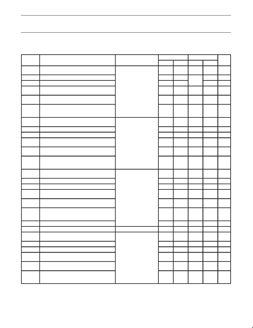
SWITCHING CHARACTERISTICS OVER OPERATING RANGE – INDUSTRIAL
3,4
T
amb
= –40
°
C to +85
°
C, V
CC
= 3.3 V
±
0.3 V, unless otherwise specified
SYMBOL
PARAMETER
CONDITIONS
1
2.5 V
±
0.2 V
MIN
2
1.5
3.3 V
±
0.3 V
MIN
2
1.3
UNIT
MAX
2.7
MAX
2.5
t
PLH
t
PHL
t
R
t
F
t
SK(o)
Propagation delay
50 to V
CC
/2; C
L
= 10 pF
(See Figure 2)
ns
Output rise time
or
–
1.0
–
1.0
ns
Output fall time
50 AC t
C
L
= 10 pF (See Figure 3);
i
ti
–
1.0
1.0
ns
Output skew: skew between outputs of same
package (same transition)
Pulse skew: skew between opposite transitions
of same output (|t
PHL
–t
PLH
|)
Package skew: skew between outputs of different
packages at same power supply voltage,
temperature, package type and speed grade
–
0.12
–
0.12
ns
t
SK(p)
f
≤
150 MHz; Outputs
connected in groups of two
–
0.3
–
0.45
ns
t
SK(t)
–
0.6
–
0.6
ns
t
PLH
t
PHL
t
R
t
F
t
SK(o)
Propagation delay
50 to V
CC
/2; C
L
= 22 pF
(See Figure 2)
1.5
3.5
1.5
3
ns
Output rise time
or
–
1.0
–
1.0
ns
Output fall time
50 AC
C
L
= 22 pF (See Figure 3);
i
i
–
1.0
–
1.0
ns
Output skew: skew between outputs of same
package (same transition)
Pulse skew: skew between opposite transitions
of same output (|t
PHL
–t
PLH
|)
Package skew: skew between outputs of different
packages at same power supply voltage,
temperature, package type and speed grade
–
0.12
–
0.12
ns
t
SK(p)
f
≤
150 MHz; Outputs
connected in groups of two
–
0.3
–
0.45
ns
t
SK(t)
–
0.6
–
0.6
ns
t
PLH
t
PHL
t
R
t
F
t
SK(o)
Propagation delay
C
L
= 30 pF; f
≤
67 MHz
(See Figure 4)
1.5
4.0
1.5
4
ns
Output rise time
–
1.0
–
1.0
ns
Output fall time
–
1.0
–
1.0
ns
Output skew: skew between outputs of same
package (same transition)
Pulse skew: skew between opposite transitions
of same output (|t
PHL
–t
PLH
|)
Package skew: skew between outputs of different
packages at same power supply voltage,
temperature, package type and speed grade
–
0.35
–
0.35
ns
t
SK(p)
–
0.35
–
0.35
ns
t
SK(t)
–
1.0
–
0.75
ns
t
jitter
f
MAX
t
PLH
t
PHL
t
R
t
F
t
SK(o)
RMS jitter
–
1.0
–
1.0
ps
Maximum output frequency
Functional to 400 MHz
C
= 50 pF; f
≤
40 MHz
(See Figure 5)
–
400
–
400
MHz
Propagation delay
1.5
4.5
1.5
4.0
ns
Output rise time
–
1.5
–
1.5
ns
Output fall time
–
1.5
–
1.5
ns
Output skew: skew between outputs of same
package (same transition)
Pulse skew: skew between opposite transitions
of same output (|t
PHL
–t
PLH
|)
Package skew: skew between outputs of different
packages at same power supply voltage,
temperature, package type and speed grade
–
0.35
–
0.35
ns
t
SK(P)
–
0.75
–
0.75
ns
t
SK(T)
–
1
–
0.75
ns
NOTES:
1. See test circuits and waveforms.
2. Minimum limits are guaranteed but not tested on Propagation Delays.
3. t
PLH
, t
PHL
, t
SK(t)
are production tested. All other parameters guaranteed but not production tested.
4. Propagation delay range indicated by Min and Max limit is due to V
CC
, operating temperature and process parameters. These propagation
delay limits do not imply skew.
相關(guān)PDF資料 |
PDF描述 |
|---|---|
| PCK604D | Analog IC |
| PCK604P | Analog IC |
| PCK604S | Analog IC |
| PCL-3M | Pulse Generator |
| PCL-80K | Pulse Generator |
相關(guān)代理商/技術(shù)參數(shù) |
參數(shù)描述 |
|---|---|
| PCK3807APW,112 | 功能描述:時鐘緩沖器 1:10 LVTTL CLK DISTR RoHS:否 制造商:Texas Instruments 輸出端數(shù)量:5 最大輸入頻率:40 MHz 傳播延遲(最大值): 電源電壓-最大:3.45 V 電源電壓-最小:2.375 V 最大功率耗散: 最大工作溫度:+ 85 C 最小工作溫度:- 40 C 封裝 / 箱體:LLP-24 封裝:Reel |
| PCK3807APW,118 | 功能描述:時鐘緩沖器 1:10 LVTTL CLK DISTR RoHS:否 制造商:Texas Instruments 輸出端數(shù)量:5 最大輸入頻率:40 MHz 傳播延遲(最大值): 電源電壓-最大:3.45 V 電源電壓-最小:2.375 V 最大功率耗散: 最大工作溫度:+ 85 C 最小工作溫度:- 40 C 封裝 / 箱體:LLP-24 封裝:Reel |
| PCK3807APW-T | 功能描述:時鐘緩沖器 1:10 LVTTL CLK DISTR DEVICE RoHS:否 制造商:Texas Instruments 輸出端數(shù)量:5 最大輸入頻率:40 MHz 傳播延遲(最大值): 電源電壓-最大:3.45 V 電源電壓-最小:2.375 V 最大功率耗散: 最大工作溫度:+ 85 C 最小工作溫度:- 40 C 封裝 / 箱體:LLP-24 封裝:Reel |
| PCK4 | 制造商:Brady Corporation 功能描述: |
| PCK-4 | 制造商:Brady 功能描述:Bulk 制造商:Brady Corporation 功能描述:CLEANING KIT 制造商:Brady Corporation 功能描述:Thermal Transfer Printer Cleaning Kit |
發(fā)布緊急采購,3分鐘左右您將得到回復(fù)。