- 您現(xiàn)在的位置:買賣IC網(wǎng) > PDF目錄382381 > PCF2104LU (NXP Semiconductors N.V.) LCD controller/driver PDF資料下載
參數(shù)資料
| 型號(hào): | PCF2104LU |
| 廠商: | NXP Semiconductors N.V. |
| 英文描述: | LCD controller/driver |
| 中文描述: | LCD控制器/驅(qū)動(dòng)器 |
| 文件頁(yè)數(shù): | 38/56頁(yè) |
| 文件大小: | 366K |
| 代理商: | PCF2104LU |
第1頁(yè)第2頁(yè)第3頁(yè)第4頁(yè)第5頁(yè)第6頁(yè)第7頁(yè)第8頁(yè)第9頁(yè)第10頁(yè)第11頁(yè)第12頁(yè)第13頁(yè)第14頁(yè)第15頁(yè)第16頁(yè)第17頁(yè)第18頁(yè)第19頁(yè)第20頁(yè)第21頁(yè)第22頁(yè)第23頁(yè)第24頁(yè)第25頁(yè)第26頁(yè)第27頁(yè)第28頁(yè)第29頁(yè)第30頁(yè)第31頁(yè)第32頁(yè)第33頁(yè)第34頁(yè)第35頁(yè)第36頁(yè)第37頁(yè)當(dāng)前第38頁(yè)第39頁(yè)第40頁(yè)第41頁(yè)第42頁(yè)第43頁(yè)第44頁(yè)第45頁(yè)第46頁(yè)第47頁(yè)第48頁(yè)第49頁(yè)第50頁(yè)第51頁(yè)第52頁(yè)第53頁(yè)第54頁(yè)第55頁(yè)第56頁(yè)

1
3
P
P
L
P
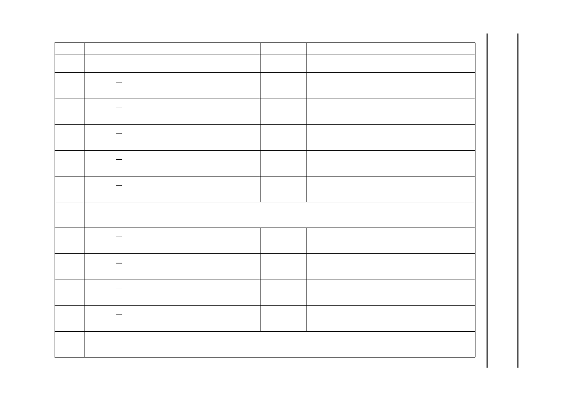
Table 7
8-bit operation, 1-line display example; using internal reset (character set ‘A’)
STEP
INSTRUCTION
DISPLAY
OPERATION
1
Power supply on (PCF2104x is initialized by the internal
reset function).
Function set:
RS = 0; R/W = 0; DB7 = 0; DB6 = 0; DB5 = 1; DB4 = 1;
DB3 = 0; DB2 = 0; DB1 = 0; DB0 = 0
Display mode on/off control:
RS = 0; R/W = 0; DB7 = 0; DB6 = 0; DB5 = 0; DB4 = 0;
DB3 = 1; DB2 = 1; DB1 = 1; DB0 = 0
Entry mode set:
RS = 0; R/W = 0; DB7 = 0; DB6 = 0; DB5 = 0; DB4 = 0;
DB3 = 0; DB2 = 1; DB1 = 1; DB0 = 0
Write data to CGRAM/DDRAM:
RS = 1; R/W = 0; DB7 = 0; DB6 = 1; DB5 = 0; DB4 = 1;
DB3 = 0; DB2 = 0; DB1 = 0; DB0 = 0
Write data to CGRAM/DDRAM:
RS = 1; R/W = 0; DB7 = 0; DB6 = 1; DB5 = 1; DB4 = 1;
DB3 = 1; DB2 = 0; DB1 = 0; DB0 = 0
Initialized. No display appears.
2
Sets to 8-bit operation, selects 2
×
12 display.
3
_
Turns on display and cursor. Entire display is blank after
initialization.
4
_
Sets mode to increment the address by 1 and to shift the
cursor to the right at the time of the write to the
DD/CGRAM. Display is not shifted.
Writes ‘P’. The DDRAM has already been selected by
initialization at power-on. The cursor is incremented by 1
and shifted to the right.
Writes ‘H’.
5
P_
6
PH_
7
|
|
|
8
Write data to CGRAM/DDRAM:
RS = 1; R/W = 0; DB7 = 0; DB6 = 1; DB5 = 0; DB4 = 1;
DB3 = 0; DB2 = 0; DB1 = 1; DB0 = 1
Entry mode set:
RS = 0; R/W = 0; DB7 = 0; DB6 = 0; DB5 = 0; DB4 = 0;
DB3 = 0; DB2 = 1; DB1 = 1; DB0 = 1
Write data to CGRAM/DDRAM:
RS = 1; R/W = 0; DB7 = 0; DB6 = 0; DB5 = 1; DB4 = 0;
DB3 = 0; DB2 = 0; DB1 = 0; DB0 = 0
Write data to CGRAM/DDRAM:
RS = 1; R/W = 0; DB7 = 0; DB6 = 1; DB5 = 0; DB4 = 0;
DB3 = 1; DB2 = 1; DB1 = 0; DB0 = 1
PHILIPS_
Writes ‘S’.
9
PHILIPS_
Sets mode for display shift at the time of write.
10
HILIPS _
Writes space.
11
ILIPS
M_
Writes ‘M’.
12
|
|
|
相關(guān)PDF資料 |
PDF描述 |
|---|---|
| PCF2104N | LCD controller/driver |
| PCF2104NU | LCD controller/driver |
| PCF2105 | LCD controller/driver |
| PCF2105MU | LCD controller/driver |
| PCF26100 | Bluetooth Adapter IC |
相關(guān)代理商/技術(shù)參數(shù) |
參數(shù)描述 |
|---|---|
| PCF2104LU/12 | 制造商:未知廠家 制造商全稱:未知廠家 功能描述:LCD Display Driver |
| PCF2104LU/2 | 制造商:MOTOROLA 制造商全稱:Motorola, Inc 功能描述:LCD controller/driver |
| PCF2104LU/7 | 制造商:MOTOROLA 制造商全稱:Motorola, Inc 功能描述:LCD controller/driver |
| PCF2104N | 制造商:PHILIPS 制造商全稱:NXP Semiconductors 功能描述:LCD controller/driver |
| PCF2104NU | 制造商:PHILIPS 制造商全稱:NXP Semiconductors 功能描述:LCD controller/driver |
發(fā)布緊急采購(gòu),3分鐘左右您將得到回復(fù)。