- 您現(xiàn)在的位置:買賣IC網(wǎng) > PDF目錄367804 > PCA1467 (NXP Semiconductors N.V.) 32 kHz watch circuits with adaptive motor pulse PDF資料下載
參數(shù)資料
| 型號: | PCA1467 |
| 廠商: | NXP Semiconductors N.V. |
| 英文描述: | 32 kHz watch circuits with adaptive motor pulse |
| 中文描述: | 32千赫的自適應(yīng)電機脈沖手表電路 |
| 文件頁數(shù): | 14/24頁 |
| 文件大小: | 132K |
| 代理商: | PCA1467 |
1998 Apr 21
14
Philips Semiconductors
Product specification
32 kHz watch circuits with adaptive motor
pulse
PCA146x series
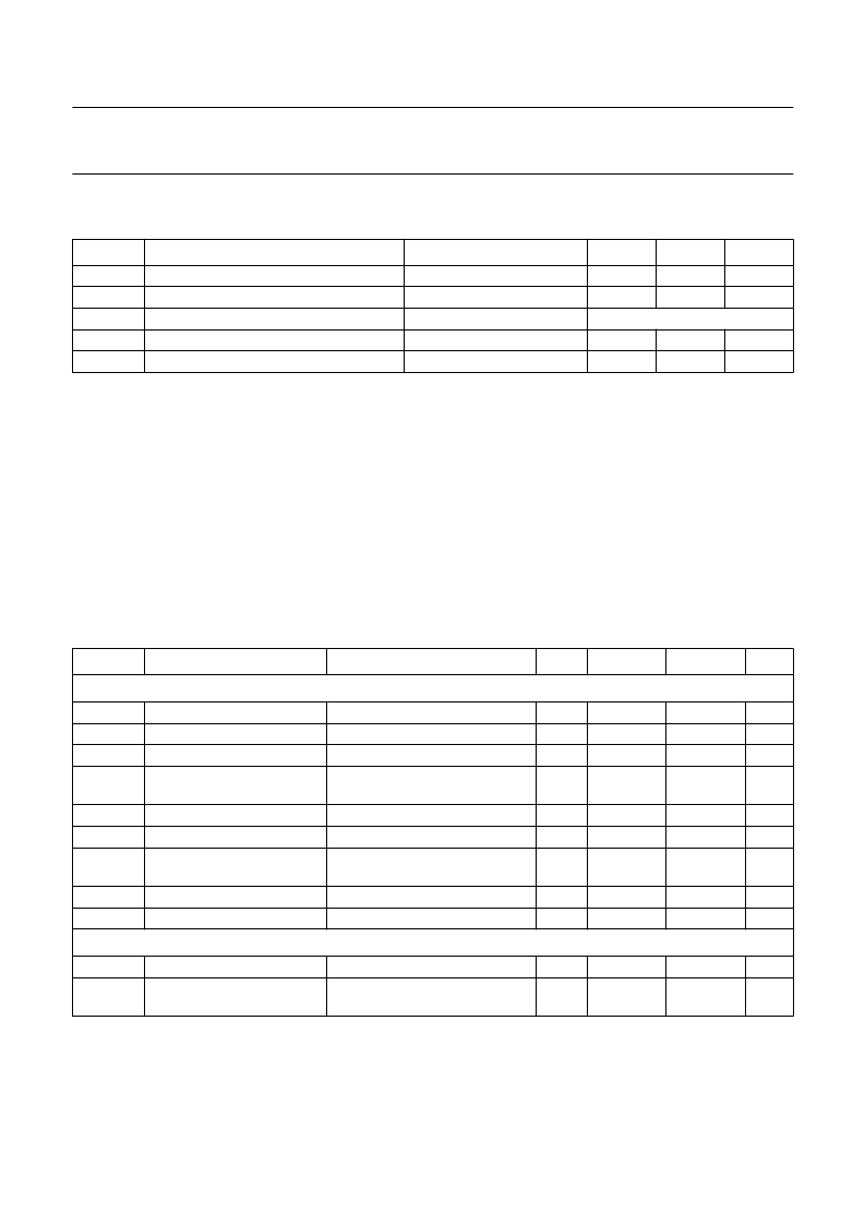
LIMITING VALUES
In accordance with the Absolute Maximum Rating System (IEC 134).
Note
1.
Connecting the battery with reversed polarity does not destroy the circuit, but in this condition a large current flows,
which will rapidly discharge the battery.
HANDLING
Inputs and outputs are protected against electrostatic discharges in normal handling. However, to be totally safe, it is
advisable to take handling precautions appropriate to handling MOS devices. Advice can be found in
“Data Handbook IC16, General, Handling MOS Devices”
CHARACTERISTICS
V
DD
= 1.55 V; V
SS
= 0 V; f
osc
= 32.768 kHz; T
amb
= 25
°
C; crystal: R
S
= 20 k
; C
1
= 2 to 3 fF; C
L
= 8 to 10 pF;
C
0
= 1 to 3 pF; unless otherwise specified.
Immunity against parasitic impedance = 20 M
between adjacent pins.
SYMBOL
PARAMETER
CONDITIONS
MIN.
MAX.
UNIT
V
DD
V
I
supply voltage
all input voltages
output short-circuit duration
operating ambient temperature
storage temperature
V
SS
= 0 V; note 1
1.8
V
SS
+6
V
DD
indefinite
+60
+100
V
V
T
amb
T
stg
10
30
°
C
°
C
SYMBOL
PARAMETER
CONDITIONS
MIN.
TYP.
MAX.
UNIT
Supply
V
DD1
V
DD
V
DD2
V
DDP
supply voltage
supply voltage variation
supply voltage
supply voltage pulse
variation
supply current
supply current
supply current
T
amb
=
10 to +60
°
C
transient within 1.2 V and 2.5 V
programming
programming
1.2
5.0
0.55
1.55
5.1
0.6
2.5
0.25
5.2
0.65
V
V
V
V
I
DD1
I
DD2
I
DD3
between motor pulses
V
DD
= 2.1 V
stop mode; pin 8 connected to
V
DD
V
DD
= 2.1 V
T
amb
=
10 to +60
°
C
170
190
180
260
300
280
nA
nA
nA
I
DD4
I
DD5
supply current
supply current
220
360
600
nA
nA
Motor output
V
sat
Z
o(sc)
saturation voltage
Σ
(P + N)
output short-circuit
impedance
R
M
= 2 k
; T
amb
=
10 to +60
°
C
between motor pulses
I
transistor
< 1 mA
150
200
200
300
mV
相關(guān)PDF資料 |
PDF描述 |
|---|---|
| PCA1485 | 32 kHz watch circuits with adaptive motor pulse |
| PCA1486 | 32 kHz watch circuits with adaptive motor pulse |
| PCA1487 | 32 kHz watch circuits with adaptive motor pulse |
| PCA1532P | CLOCK CIRCUIT|CMOS|DIP|8PIN |
| PCA159XSERIES | Watch Circuit |
相關(guān)代理商/技術(shù)參數(shù) |
參數(shù)描述 |
|---|---|
| PCA1467U/10 | 制造商:PHILIPS 制造商全稱:NXP Semiconductors 功能描述:32 kHz watch circuits with adaptive motor pulse |
| PCA146XSERIES | 制造商:未知廠家 制造商全稱:未知廠家 功能描述:Watch Circuit |
| PCA1484T | 制造商:未知廠家 制造商全稱:未知廠家 功能描述:Watch Circuit |
| PCA1485 | 制造商:PHILIPS 制造商全稱:NXP Semiconductors 功能描述:32 kHz watch circuits with adaptive motor pulse |
| PCA1485T | 制造商:未知廠家 制造商全稱:未知廠家 功能描述:Watch Circuit |
發(fā)布緊急采購,3分鐘左右您將得到回復。